
Implant Planning Using Captured Joint Motion Information

a technology of motion information and implants, applied in the field of surgical computer systems, can solve the problems of reducing the surgeon's ability to view and access the anatomy of the joint, increasing the complexity of assessing the proper position of the implant and reshaping the bone, and long recovery time for the patien

Active Publication Date: 2008-10-23
MAKO SURGICAL CORP
View PDF20 Cites 163 Cited by
  • Summary
  • Abstract
  • Description
  • Claims
  • Application Information

AI Technical Summary

Benefits of technology

[0083]The invention has been described in terms of particular embodiments. The alternatives described herein are examples for illustration only and not to limit the alternatives in any way. The steps of the invention can be performed in a different order and still achieve desirable results. Other embodiments are within the scope of the following claims.

Problems solved by technology

The invasive nature of the incision results in a lengthy recovery time for the patient.
However, the smaller incision size reduces a surgeon's ability to view and access the anatomy of a joint.
Consequently, the complexity of assessing proper implant position and reshaping bone increases, and accurate placement of implants may be more difficult.
Inaccurate positioning of implants may lead to reduced range of motion of a joint, impingement, and subsequent dislocation.
For example, one problem with total hip replacement is dislocation of a femoral implant from an acetabular cup implant caused, for example, by impingement, which in turn may be caused by inaccurate positioning of the acetabular cup implant within a pelvis.
Another drawback of both MIS and traditional orthopedic surgical approaches is that such approaches do not enhance the surgeon's inherent surgical skill in a cooperative manner.
Although such systems enable precise bone resections for improved implant fit and placement, they act autonomously (rather than cooperatively with the surgeon) and thus require the surgeon to cede a degree of control to the robot.
One drawback of conventional interactive robotic systems is that such systems lack the ability to adapt surgical planning and navigation in real-time to a dynamic intraoperative environment.
The interactive robotic system requires a relevant anatomy to be rigidly restrained and the robotic system to be fixed in a gross position and thus lacks real-time adaptability to the intraoperative scene.
Moreover, a three degree of freedom arm configuration and the requirement that the surgeon manipulate the arm using a force handle results in limited flexibility and dexterity, making the robotic system unsuitable for certain MIS applications such as intraoperative implant planning.
As a result of anatomical variation, there is no single implant design or orientation of implant components that provides an optimal solution for all patients.
Implant planning based on such types of conventional devices can lead to a large discrepancy between desired and actual implant placement, possibly resulting in reduced range of motion of a joint, impingement, and dislocation.
Moreover, simulated joint movement does not account for actual motion of a joint with individual variations.
Although the Glassman patents describe a system that may offer the potential for increased accuracy and consistency in the preparation of bones to receive implants, the system lacks real-time adaptability to the intraoperative scene and consistent, predictable results regardless of surgical skill level because the surgeon manually has to interact and analyze relative discrete positions of implants in a joint rather than analyzing the implants during continuous motion of the joint.

Method used


Image

  • Implant Planning Using Captured Joint Motion Information
  • Implant Planning Using Captured Joint Motion Information
  • Implant Planning Using Captured Joint Motion Information

Examples


Embodiment Construction

[0041]Presently preferred embodiments are illustrated in the drawings. Although this specification refers primarily to unicondylar knee joint replacement surgery, it should be understood that the subject matter described herein is applicable to other joints in the body, such as, for example, a shoulder, elbow, wrist, spine, hip, or ankle and to any other orthopedic and / or musculoskeletal implant, including implants of conventional materials and more exotic implants, such as orthobiologics, drug delivery implants, and cell delivery implants.

Representation of a Joint and Implant Models

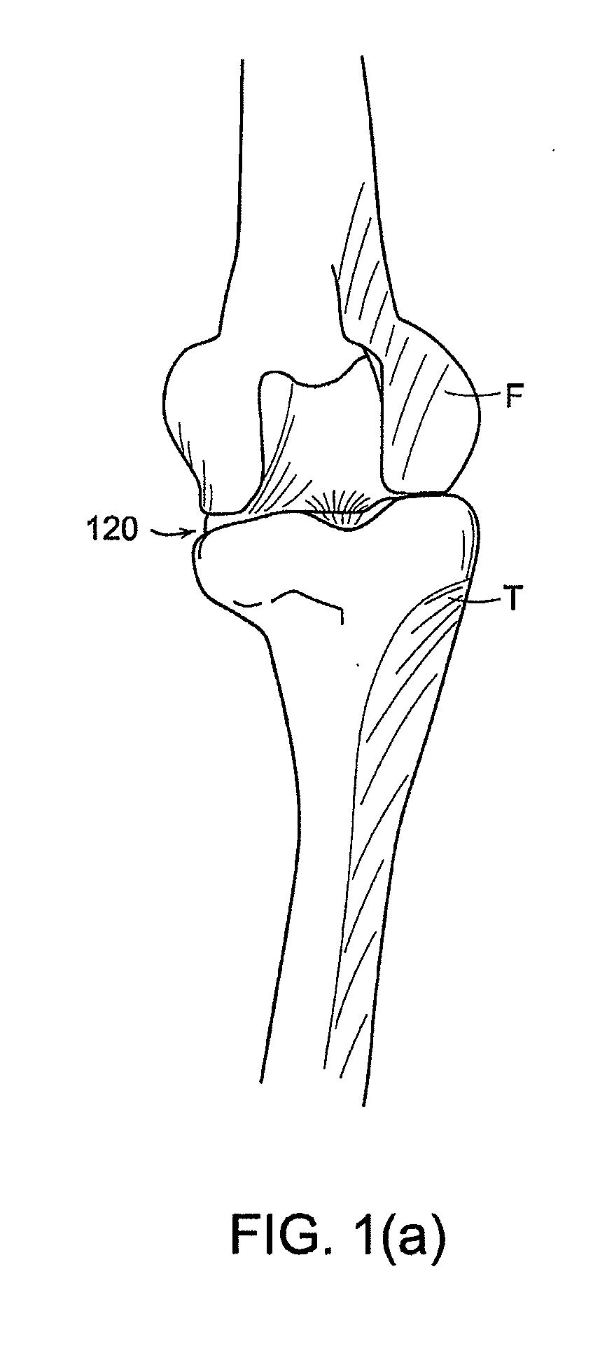
[0042]FIG. 1(a) shows a front view of a tibia T (e.g., a first bone) and a femur F (e.g., a second bone) of a joint 120 without any implant and with the joint 120 at full extension (i.e., a flexion angle θ of 0 degrees). Position trackers (e.g., such as those shown in FIG. 15 and described in more detail below) that are detectable by a detection device, such as an optical camera, are affixed to the femur...


PUM


Abstract

The description relates to surgical computer systems, including computer program products, and methods for implant planning using captured joint motion information. Data is captured representative of a range of motion of a joint associated with a particular individual, where the joint includes a first bone and a second bone. The first bone of the joint is represented and a first implant model is associated with the representation of the first bone. Based on the captured data, a relationship is determined between the first implant model and a representation of the second bone through at least a portion of the range of motion of the joint. Information is displayed representative of the determined relationship.

Description

CROSS REFERENCE TO RELATED APPLICATIONS[0001]The present application claims priority to U.S. Provisional Patent Application Ser. No. 60 / 925,269, filed on Apr. 19, 2007, which is hereby incorporated by reference herein in its entirety.BACKGROUND OF THE INVENTION[0002]1. Field of the Invention[0003]The invention relates to surgical computer systems, including computer program products, and methods for implant planning using captured joint motion information.[0004]2. Description of Related Art[0005]Orthopedic joint replacement surgery may involve arthroplasty of a knee, hip, or other joint (e.g., shoulder, elbow, wrist, ankle, fingers, etc.). For example, traditional total knee arthroplasty involves a long incision, typically in a range of about 6 to 12 inches, to expose the joint for bone preparation and implantation of implant components. The invasive nature of the incision results in a lengthy recovery time for the patient. Minimally invasive surgery (MIS) reduces the incision lengt...

Claims


Application Information

Patent Timeline
IPC IPC(8): G06G7/48G16Z99/00
CPCA61B19/50A61B19/52A61B19/5244A61B2019/501A61B2019/562A61B2019/504A61B2019/505A61B2019/508A61B2019/5255A61B2019/502A61B2034/101A61B2034/102A61B2034/104A61B90/36A61B2034/2055A61B34/20A61B2034/105A61B2034/108A61B2034/252A61B2034/107A61B34/10G16H50/50G16Z99/00A61B90/00A61F2/3859A61F2/389
Inventor ARATA, LOUISMOZES, ALONOTTO, JASONVAN VORHIS, ROBERT
Owner MAKO SURGICAL CORP
Features
  • Generate Ideas
  • Intellectual Property
  • Life Sciences
  • Materials
  • Tech Scout
  • Unparalleled Data Quality
  • Higher Quality Content
  • 60% Fewer Hallucinations
Learn More