Reconfigurable Computing Architectures: Dynamic and Steering Vector Methods

a computing architecture and vector method technology, applied in computing, digital computers, instruments, etc., to achieve the effect of increasing hardware complexity, facilitating future usability, and effectively creating a dynamic priority loading and discarding process

Inactive Publication Date: 2008-10-23
THE BOARD OF RGT UNIV OF OKLAHOMA
View PDF1 Cites 39 Cited by
  • Summary
  • Abstract
  • Description
  • Claims
  • Application Information

AI Technical Summary

Benefits of technology

[0026]In accordance with the present invention, a proposed solution to the steering vector scoring problem is to further segregate the instructions into subsets based on their level within a directed acyclic graph representative of the instruction buffer. The instructions within the buffer are then sorted into dependency levels, and the RFU need of each level is computed and then passed onto a loading scheme that allows RFUs to be loaded individually into any location in the configuration space. The RFUs that are already configured are then evaluated based on the computed RFU need for each dependency level, and their future usability is assessed so that valuable RFUs are not discarded, effectively creating a dynamic priority loading and discarding process.
[0027]The dynamic vector method of reference [2] makes use of both the configuration space complexity results and the data obtained from simulating the steering vector approach with many different steering vector selection techniques. The dynamic vector method is the main contribution of this research and builds heavily on the work in reference [1] and in itself contains further contributions such as a unique level analysis procedure and a priority based dynamic vector update procedure. The ultimate goal of this work will be to realize the dynamic vector method in a dynamically reconfigurable field programmable gate array (FPGA). The design of the level analysis procedure in conjunction with the RFU need calculation as a combinational circuit will facilitate the, “on-the-fly,” creation of either a partial or complete RFU vector that can then be loaded into the available configuration slots. Finally, the dynamic vector can then be tested in a true high performance hardware application, perhaps in a high performance reconfigurable device.
[0028]In another version of the present invention, an architectural framework is studied that can perform dynamic reconfiguration. A basic objective is to dynamically reconfigure the architecture so that its configuration is well matched with the current computational requirements. The reconfigurable resources of the architecture are partitioned into N slots. The configuration bits for each slot are provided through a connection to one of N independent busses, where each bus can select from among K configurations for each slot. Increasing the value of K can increase the number of configurations that the architecture can reach, but at the expense of more hardware complexity to construct the busses. Our study reveals that it is often possible for the architecture to closely track ideal desired configurations even when K is relatively small (e.g., two or four). The input configurations to the collection of busses are defined as steering vectors; thus, there are K steering vectors, each having N equal sized partitions of configuration bits. In accordance with the present invention, a combinatorial approach is introduced for designing steering vectors that enables the designer to evaluate trade-offs between performance and hardware complexity associated with the busses.

Problems solved by technology

The specific challenge addressed is the design of a control unit that loads and discards RFUs within a configuration space based on a table of incoming program instructions.

Method used


Image

  • Reconfigurable Computing Architectures: Dynamic and Steering Vector Methods
  • Reconfigurable Computing Architectures: Dynamic and Steering Vector Methods
  • Reconfigurable Computing Architectures: Dynamic and Steering Vector Methods

Examples


case study

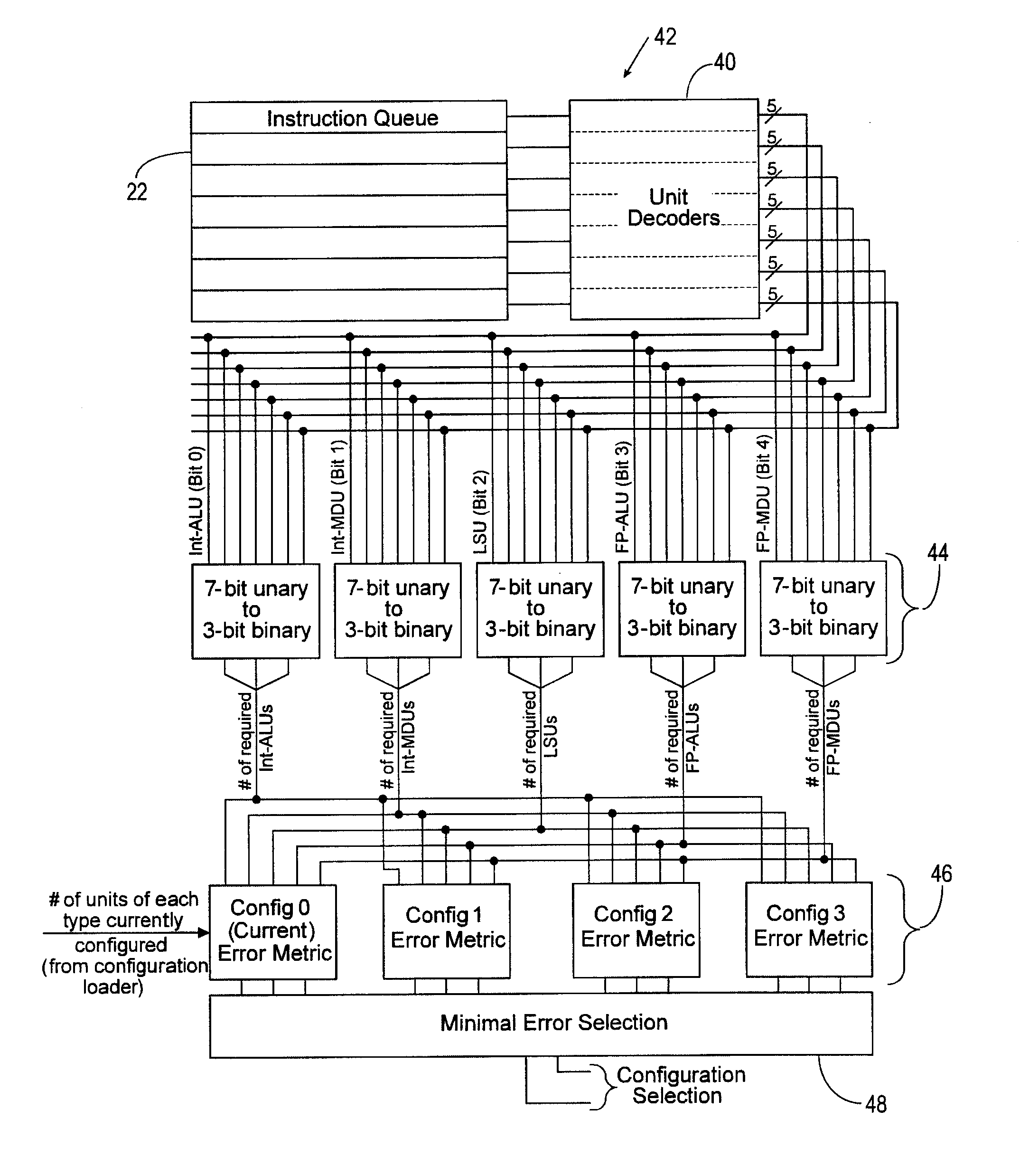
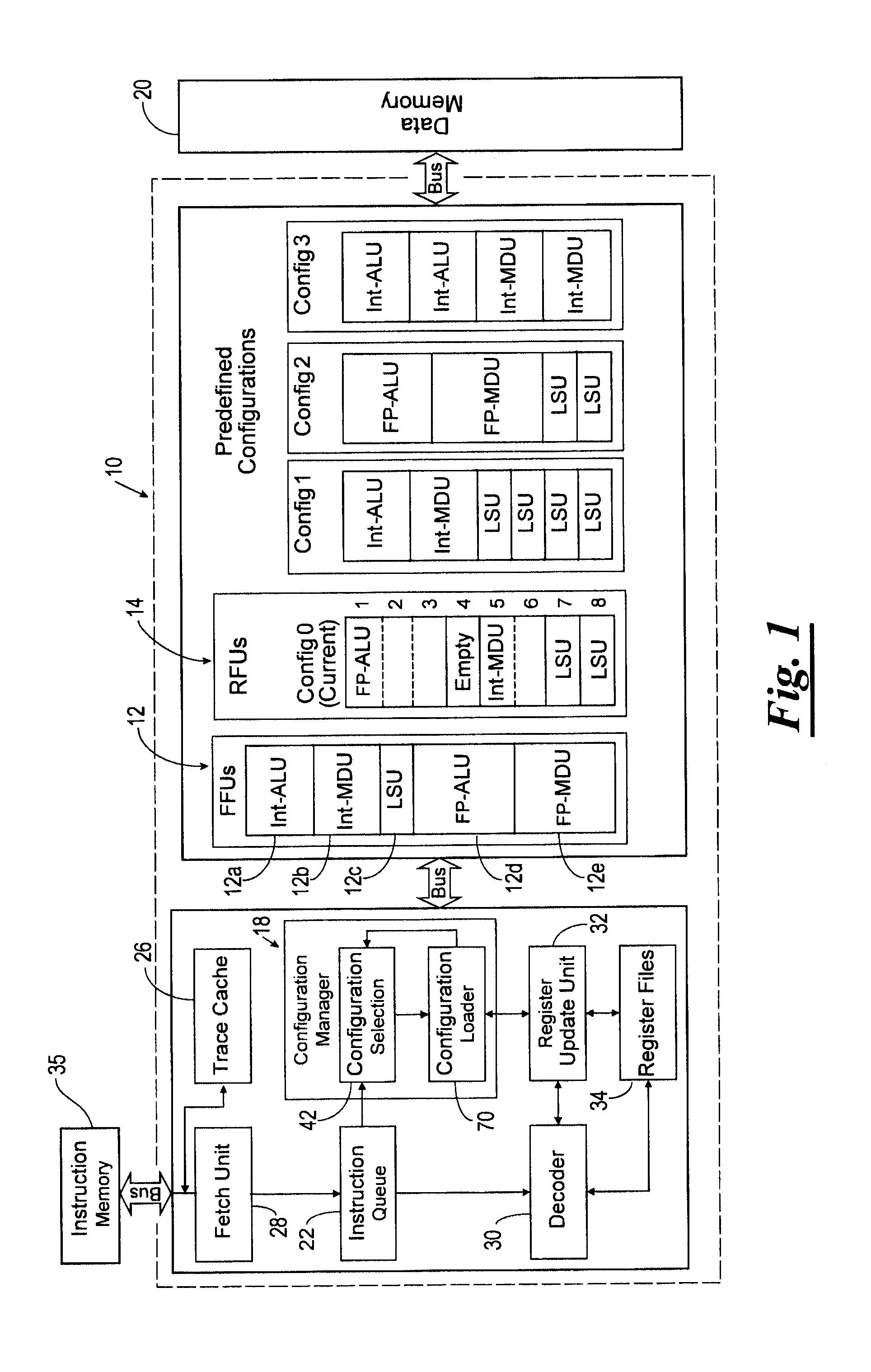
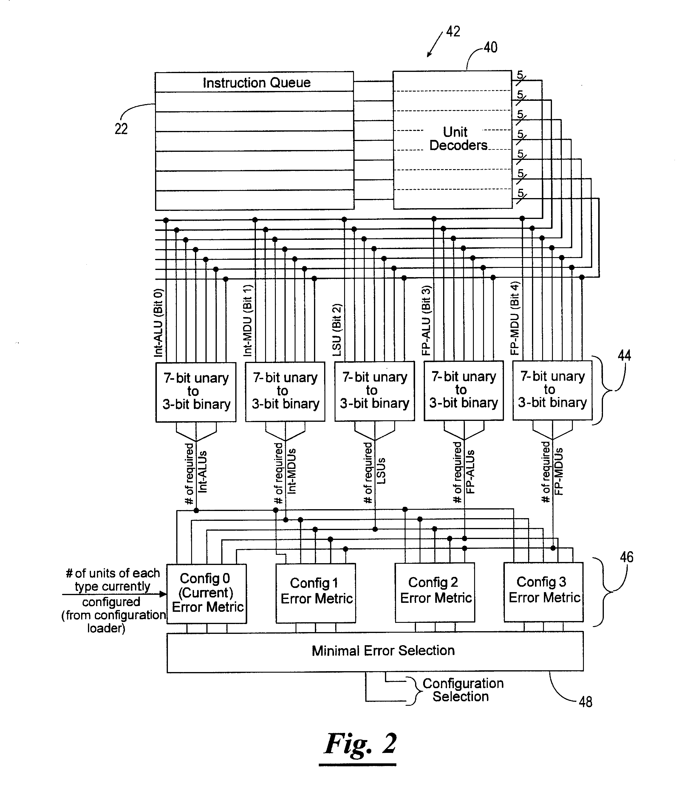
[0212]A general-purpose processor architecture with dynamically reconfigurable functional units was proposed in reference [3]. This basic concept was studied further and extended in references [1] and [2]. For the case study presented in this section, it is assumed that the reconfigurable processor has N=5 slots and that the objective is to design K=2 steering vectors that are well matched to the configurations determined to be important. The specific objective is to exploit as much instruction-level parallelism as possible by being able to reach important configurations, i.e., those configurations that enable as many instructions to be executed in parallel as possible. For example, if it is the case that multiplication instructions can never (or rarely) be executed in parallel, but parallel addition instructions can often be executed in parallel, then the choice of steering vectors 230 should comprehend this reality and enable configurations with two or more adder units to be reach...


PUM


Abstract

A reconfigurable processor including a plurality of reconfigurable slots, a memory, an instruction queue, a configuration selection unit, and a configuration loader. The plurality of reconfigurable slots are capable of forming reconfigurable execution units. The memory stores a plurality of steering vector processing hardware configurations for configuring the reconfigurable execution units. The instruction queue stores a plurality of instructions to be executed by at least one of the reconfigurable execution units. The configuration selection unit analyzes the dependency of instructions stored in the instruction queue to determine an error metric value for each of the steering vector processing hardware configurations indicative of an ability of a reconfigurable slot configured with the steering vector processing hardware configuration to execute the instructions in the instruction queue, and chooses one of the steering vector processing hardware configurations based upon the error metric values. The configuration loader determines whether one or more of the reconfigurable slots are available and reconfigures at least one of the reconfigurable slots with at least a part of the chosen steering vector processing hardware configuration responsive to at least one of the reconfigurable slots being available.

Description

CROSS-REFERENCE TO RELATED APPLICATIONS[0001]The present patent application claims priority to the provisional patent application identified by U.S. Ser. No. 60 / 923,461 filed on Apr. 13, 2007, the entire content of which is hereby incorporated herein by reference.STATEMENT REGARDING FEDERALLY SPONSORED RESEARCH OR DEVELOPMENT[0002]Not Applicable.THE NAMES OF THE PARTIES TO A JOINT RESEARCH AGREEMENT[0003]Not Applicable.REFERENCE TO A “SEQUENCE LISTING,” A TABLE, OR A COMPUTER PROGRAM LISTING APPENDIX SUBMITTED ON A COMPACT DISC AND AN INCORPORATION-BY-REFERENCE OF THE MATERIAL ON THE COMPACT DISC (SEE § 1.52(e)(5)). THE TOTAL NUMBER OF COMPACT DISCS INCLUDING DUPLICATES AND THE FILES ON EACH COMPACT DISC SHALL BE SPECIFIED[0004]Not Applicable.BACKGROUND OF THE INVENTION[0005]In one aspect, the present invention focuses on analyzing incoming instruction dependency information to identify both present and future instruction level parallelism (ILP). The analysis of instruction dependen...

Claims


Application Information

Patent Timeline
Patent Type & Authority Applications(United States)
IPC IPC(8): G06F15/76G06F9/02
CPCG06F9/3836G06F9/3897G06F15/7867G06F9/3838G06F9/3857G06F9/3858
Inventor MOULD, NICK A.ANTONIO, JOHN K.TULL, MONTE P.VEALE, BRIAN F.JUNGER, JOHN R.
Owner THE BOARD OF RGT UNIV OF OKLAHOMA
Why Eureka
Try Eureka