Electrode with increased stability and method of manufacturing the same

a technology of stability and electrodes, applied in the field of electrodes with increased stability and manufacturing the same, can solve the problems of tissue damage, large prosthetic devices, bulky, etc., and achieve the effect of improving the adhesion of the electrode material and high stability

Active Publication Date: 2008-10-30
CORTIGENT INC
View PDF8 Cites 4 Cited by
  • Summary
  • Abstract
  • Description
  • Claims
  • Application Information

AI Technical Summary

Benefits of technology

[0018]The present invention provides electrode designs and methods for manufacturing electrodes with higher stability and improved adhesion of the electrode material on the substrate.
[0023]Another aspect of the present invention is a method of manufacturing an electrode with increased stability, comprising:a) depositing a metal layer on an base layer;b) applying photoresist layer on the metal layer;c) patterning the photoresist layer providing openings;d) electroplating the openings with metal;e) removing the photoresist layer leaving spaces; andf) filling the spaces with polymer.
[0024]Another aspect of the present invention is a method of manufacturing an electrode with increased stability, comprising:a) depositing a metal layer on an base layer;b) applying a polymer layer on the metal layer;b) applying photoresist layer on the polymer layer;c) patterning the photoresist layer providing openings;d) electroplating the openings with metal; ande) removing the photoresist layer.

Problems solved by technology

While some of these early attempts met with some limited success, these early prosthetic devices were large, bulky and could not produce adequate simulated vision to truly aid the visually impaired.
Edge effect can cause tissue damage due to uneven current distribution.
Thin film techniques may not provide enough electrode materials on the electrode surface for chronic stimulation.
Further, common electroplating technique presents stress problem that limits the plated layer to less than 1 μm.

Method used


Image

  • Electrode with increased stability and method of manufacturing the same
  • Electrode with increased stability and method of manufacturing the same
  • Electrode with increased stability and method of manufacturing the same

Examples


example

General Procedure

Platinum Plating Solution Preparation

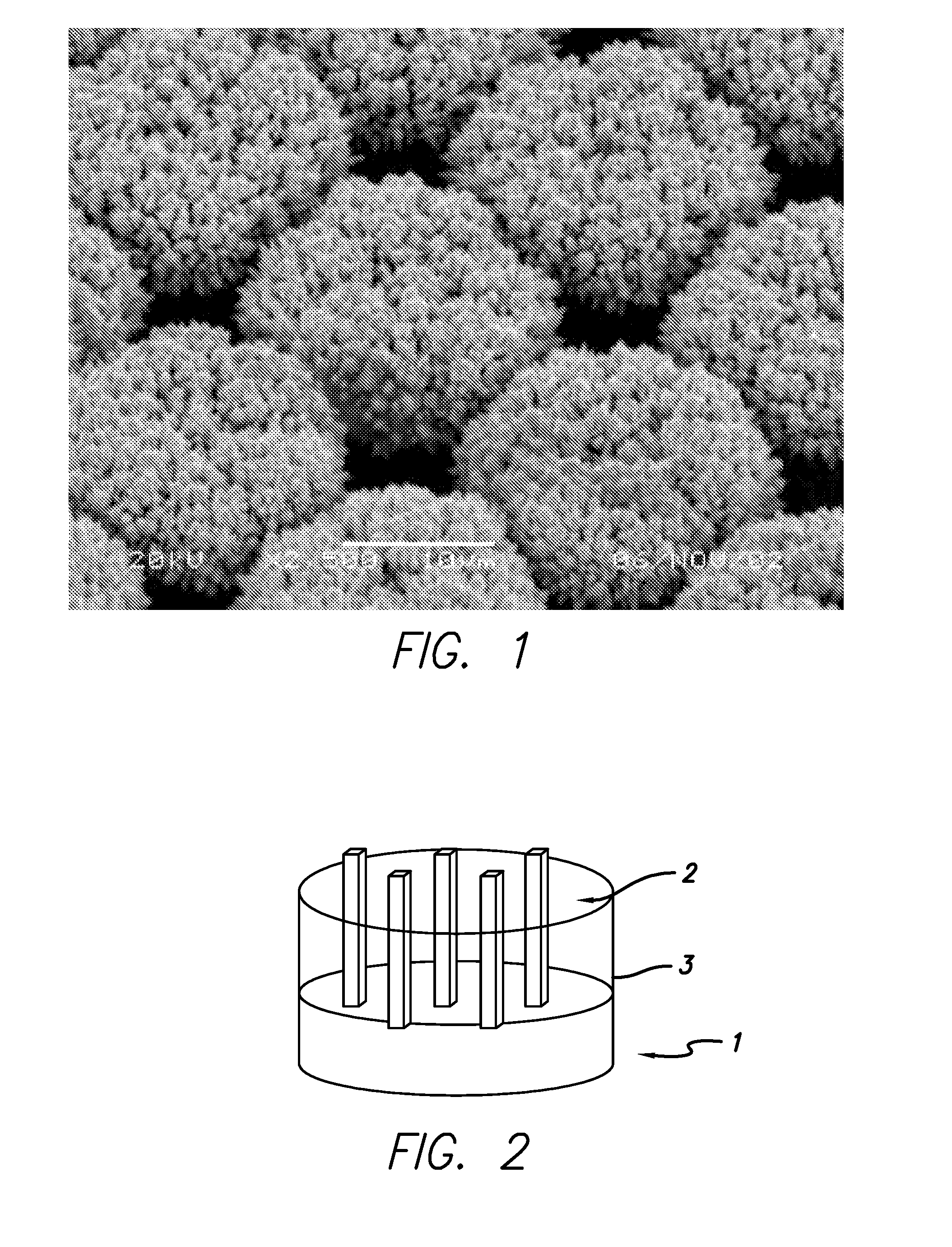
[0058]0.3 g sodium dihydrogen phosphate (NaH2PO4) and 6.03 g disodium hydrogen phosphate (Na2HPO4) [Fluka] were dissolved in 100 ml deionized water, and stirred by magnetic stirring for 30 minutes. The concentrations for NaH2PO4 and Na2HPO4 were 25 mM and 425 mM. Then 0.5 g of Platinum chloride (PtCl4) [Alfa Aesar] was added to the phosphate solution to form the platinum salt concentrations of 15 mM. The solution was then stirred for 30 minutes. Different concentrations of (PtCl4) were used in the experiments and the range of Pt salt concentrations was from 3 to 30 mM. The pH of the solution was measured at 7.9. The color of the solution was amber. The solution was deaerated before the plating process by bubbling nitrogen through the solution.

Preparation of the Substrate

[0059]A thin-film platinum polyimide array was used for platinum plating. The array included 16 electrodes with 200 μm thin-film Pt disk as exposed electrode surf...


PUM

PropertyMeasurementUnit
thicknessaaaaaaaaaa
thickaaaaaaaaaa
thickaaaaaaaaaa

Abstract

The present invention provides an implantable electrode with increased stability having a clustered structure wherein the surface of the electrode is covered with a material comprising openings which are filled with sticks or posts.The present invention provides an implantable electrode with increased stability wherein the surface is of the electrode comprises mesh grids which are filled with sticks which are filed with a conducting or insulating material.The present invention provides a method of manufacturing an electrode with increased stability, comprising: depositing a metal layer on an base layer; applying photoresist layer on the metal layer; patterning the photoresist layer providing openings; electroplating the openings with metal; removing the photoresist layer leaving spaces; and filling the spaces with polymer.The present invention provides A method of manufacturing an electrode with increased stability, comprising: depositing a metal layer on an base layer; applying a polymer layer on the metal layer; applying photoresist layer on the polymer layer; patterning the photoresist layer providing openings; electroplating the openings with metal; and removing the photoresist layer.

Description

CROSS REFERENCE TO RELATED APPLICATIONS[0001]This application is a divisional of application Ser. No. 11 / 820,744, entitled “Electrode with Increased Stability and Method of Manufacturing the Same”, filed Jun. 19, 2007, which application claims priority to provisional Application No. 60 / 814,976 for “Method to Increase Electrode's Stability” filed on Jun. 19, 2006, and to U.S. Provisional Application No. 60 / 815,037 for “New Electrode Design” filed on Jun. 19, 2006, which are both incorporated herein by reference in their entirety.GOVERNMENT RIGHTS NOTICE[0002]This invention was made with government support under grant No. R24EY12893-01, awarded by the National Institutes of Health. The government has certain rights in the invention.FIELD OF THE INVENTION[0003]The present invention is generally directed to an electrode with increased stability and method of manufacturing the same. In particular the present invention is directed to a new electrode design.BACKGROUND OF THE INVENTION[0004...

Claims


Application Information

Patent Timeline
Patent Type & Authority Applications(United States)
IPC IPC(8): H01M4/04
CPCA61N1/0543A61N1/36046
Inventor ZHOU, DAO MINOK, JERRYTALBOT, NEIL HAMILTONMECH, BRIAN V.LITTLE, JAMES SINGLETONGREENBERG, ROBERT J.
Owner CORTIGENT INC
Why Eureka
Try Eureka