Method for Manufacturing Particulate Chemical Substances and Particulate Products of Such Substances

a technology of chemical substances and parts, applied in the direction of manufacturing tools, natural mineral layered products, cellulosic plastic layered products, etc., can solve the problems of energy consumption, the method of heating a gas possesses a problem, and the inability to obtain particulate chemical substances having a desired particle size distribution, etc., to achieve the effect of preventing dust generation

Active Publication Date: 2008-10-30
SEIKO KAGAKU
View PDF11 Cites 0 Cited by
  • Summary
  • Abstract
  • Description
  • Claims
  • Application Information

AI Technical Summary

Benefits of technology

[0008]The method of manufacturing the particulate chemical substance, and the resulting particulate chemical substance of the present invention are substantial improvements over conventional methods and products produced therefrom from the viewpoint of preventing dust generation due to crushing during transportation and handling in manufacturing plants.

Problems solved by technology

Generally, a method for heating a gas possesses a problem in the viewpoint of energy consumption, compared with the case of heating a liquid.
However, to make the molten substance into smaller droplets by giving vibration has a risk in that particulate chemical substances having a desired particle size distribution can not be obtained unless a vibration frequency is properly chosen.
However, the methods disclosed in the above-mentioned patent documents are not said to produce particulate chemical substance having narrow particle size distribution and high hardness sufficient for use in pneumatic transportation processes.

Method used


Image

  • Method for Manufacturing Particulate Chemical Substances and Particulate Products of Such Substances
  • Method for Manufacturing Particulate Chemical Substances and Particulate Products of Such Substances
  • Method for Manufacturing Particulate Chemical Substances and Particulate Products of Such Substances

Examples


example 1

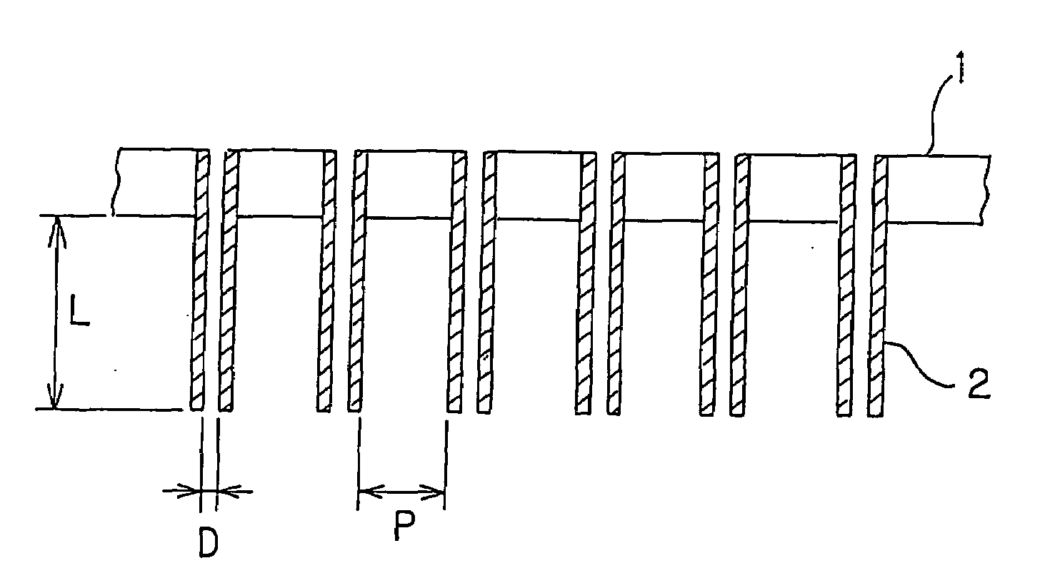
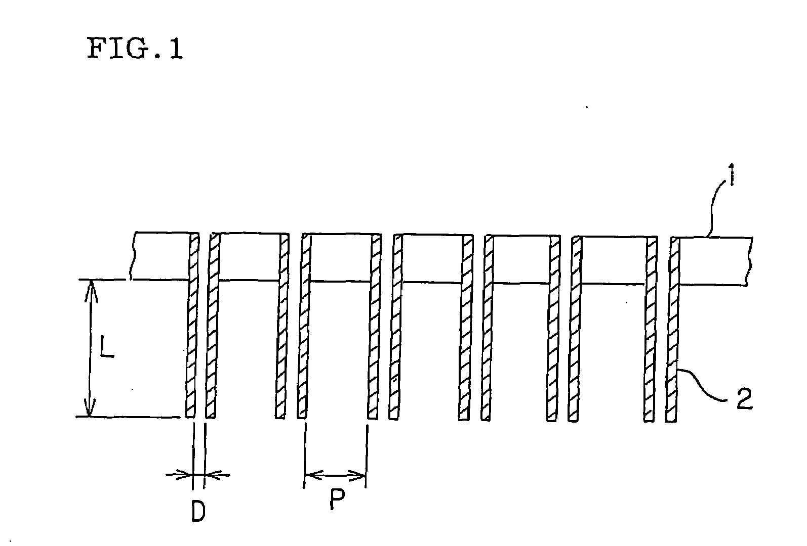
[0039]A spray granulation apparatus having a nozzle plate made of 304SS stainless steel with a thickness of 6 mm is used as a granulation apparatus. The nozzle plate is provided with pipes with an inner diameter of 0.45 mm, an outer diameter of 2.0 mm, and a length of 20 mm. A desired number of pipes are soldered as nozzle pipes. Phenothiazine, with a melting point of 182° C., is heated to 210-230° C. to melt and is dropped through the nozzle plate with nozzle pipes. The back pressure during dropping is kept at 0.05-0.1 MPa. Cold nitrogen gas is blown counter-currently into the droplets to obtain phenothiazine particles. The particle size distribution after completion of granulation is shown in the following Table 1. The phenothiazine, just after production, without sieving, is subjected to sieving using JIS Standard Sieves to determine the particle size distribution, and the result thereof is shown in Table 1 below. FIG. 3 is a graph showing thus obtained particle size distribution...

example 2

[0044]The same experiment as in Example 1 is carried out except using wax with a melting point of 75° C., which is heated to 110-130° C. to melt and dropped. The back pressure during dropping was 0.05-0.1 MPa. Cold air is blown counter-currently into the mass to obtain wax particles. The particle size distribution after completion of granulation is shown in the following Table 2. FIG. 6 is a graph showing this particle size distribution. Moreover, the microscope examination in the same manner reveals that a similar result to that in Example 1 is observed.

TABLE 2Particle diameterAmount of particles (wt %)1.7 mm − 2.0 mm15.541.4 mm − 1.7 mm77.521.0 mm − 1.4 mm5.400.5 mm − 1.0 mm1.51Less than 0.5 mm0.05


PUM

PropertyMeasurementUnit
distanceaaaaaaaaaa
distanceaaaaaaaaaa
lengthaaaaaaaaaa

Abstract

Particulate chemical substances and method of manufacturing thereof wherein the resultant particles have a narrow particle size distribution and sufficient hardness to ensure that particles can withstand intact being driven through pneumatic transportation equipment. The method comprises granulating raw material using a spray granulation apparatus having a nozzle plate equipped with nozzle pipes having a length in the range of 2-100 mm.

Description

TECHNICAL FIELD[0001]The present invention relates to a method for manufacturing particulate chemical substances using a spray granulation apparatus and to a chemical substance in particulate form having a specific particle size distribution, a desired hardness, and a substantially round cross-sectional configuration, manufactured by the inventive method.BACKGROUND ART[0002]A method for granulating a chemical substance having a melting point of 50-250° C. using a spray granulation apparatus is disclosed in Particulate Process and Technology, (supplemented revision), Chapter on Granulation, 3.3 Injection Granulation Apparatus, pages 43-50, Chemical Industry Publishing Co., Jan. 10, 1988. There is disclosed in a PCT International Patent Application Publication WO99 / 33555 a method for manufacturing a particulate chemical substance having a quite limited particle size distribution, which comprises the step of dropping a molten chemical from a nozzle plate, and blowing a cooling medium t...

Claims


Application Information

Patent Timeline
Patent Type & Authority Applications(United States)
IPC IPC(8): B28B1/32
CPCY10T428/2982B01J2/02
Inventor HARADA, HIROSHIMIYAMOTO, SHINICHI
Owner SEIKO KAGAKU
Why Eureka
Try Eureka