Hydrodynamic Isolation Method and Apparatus

a technology of hydrodynamic isolation and apparatus, applied in the direction of positive displacement liquid engines, laboratory glassware, instruments, etc., can solve the problems of inability to accurately determine the kinetic rate, unsatisfactory structures and methods, and difficult manufacturing and breakage. , the effect of small array of microfluidic devices

Active Publication Date: 2008-10-30
BRUKER DALTONIK GMBH & CO KG
View PDF3 Cites 3 Cited by
  • Summary
  • Abstract
  • Description
  • Claims
  • Application Information

AI Technical Summary

Benefits of technology

[0019]According to a first aspect of the present invention, a flow cell device is provided that is capable of operation in a process termed “hydrodynamic isolation” in which highly discrete and small volumes of fluid are presented to isolated locations on a two-dimensional surface contained within an open fluidic chamber that has physical dimensions such that laminar style flow occurs for fluids flowing through the chamber. The device includes a number of reagent inlet ports that are disposed adjacent associated sensor substrates or detection windows. Located between the reagent inlet ports and the detection substrates are reagent evacuation ports. The evacuation ports operate to continuously withdraw a reagent being introduced into a continuous laminar flow of a guide fluid moving along the flow cell through the reagent inlet to enable the reagent to develop a clean leading edge without any appreciable concentration gradient to create problems with regard to the interaction of the sample with the detection substrate(s). Once the clean leading edge of the reagent sample has been created, the vacuum applied to the reagent sample from the evacuation port is stopped, such that the discrete volume reagent sample having the clean leading edge is introduced into the guide fluid flow to move along the flow cell and pass over the detection substrate to interact therewith. Immediately after passing the detection substrate, the reagent sample can be evacuated completely from the flow cell by another evacuation port located downstream from the detection substrate. Thus, the reagent sample is prevented from interacting with any other detection substrate present in the flow cell by removing the reagent sample from the laminar fluid flow moving through the flow cell using a vacuum, without any physical barriers within the cell to divert the fluids, and without the need for mechanical valves, which are difficult to manufacture and break easily. Therefore, the present invention enables discrete volumes of fluids to be injected through a flow cell, or addressed to a specific location within a flow cell, without the need for cumbersome and non-robust valves in the fluid tubing pathways leading up to the fluid inlet ports of the flow cell. This capability enables the design of extremely small array addressing microfluidic devices while maintaining, and in some cases exceeding, the level of functionality of other microfluidic and macrofluidic fluid delivery devices that utilize mechanical valves.

Problems solved by technology

As the concentration of this mixture is unknown, including it in the final analysis of the sample can often interfere with the accuracy and sensitivity of testing.
Often mechanical valves are used to perform this function but due to limitations in valve technology related to sample waste, valve dimensions, and poor robustness, these structures and methods are not ideal.
During these ‘transition periods’, accurate determination of kinetic rates is not possible as the true concentration of test sample exposed to the detection surface is unknown.
The vast majority of current flow based sample delivery technologies, even on a micro-fluidic level, do an inadequate job of efficiently transitioning between samples or sample and buffer.
The long transition times are mainly due to the physical design of valve technology built into the sample delivery systems, which can often only be effectively utilized at some distance from the flow cell and detection surface.
But, due to their design and small size, these valves are costly, often mechanically unreliable, and susceptible to clogging.
It has been well documented that inefficient transport of sample molecules to the sensor surface, termed “mass transport limitations”, results in inaccurate estimations of kinetics rates.
But when considering the practical applicability of flow cell based analysis techniques, the requirement to pass sample over the detection surface at high rates of speed becomes a liability.
As the physical nature of molecular interactions often means that sample molecules must be in contact for several minutes to obtain accurate measurements, high sample flow rates during analysis result in the consumption of large volumes of test sample.
But due to a variety of issues related to the different detection technologies (i.e. size of the detection substrates, electronics, and optics), and the need to interface those technologies with high performance and robust sample fluid delivery systems, there have been practical limitations to the miniaturization of detection flow cells.
However, these prior art techniques and structures shown in FIGS. 1-4g are limited to addressing sample fluid streams in single dimensions within the array.
These techniques offer no remedy to address individual x-y locations, or “spots”, on the array independently severely limiting the flexibility of array design.

Method used


Image

  • Hydrodynamic Isolation Method and Apparatus
  • Hydrodynamic Isolation Method and Apparatus
  • Hydrodynamic Isolation Method and Apparatus

Examples


first embodiment

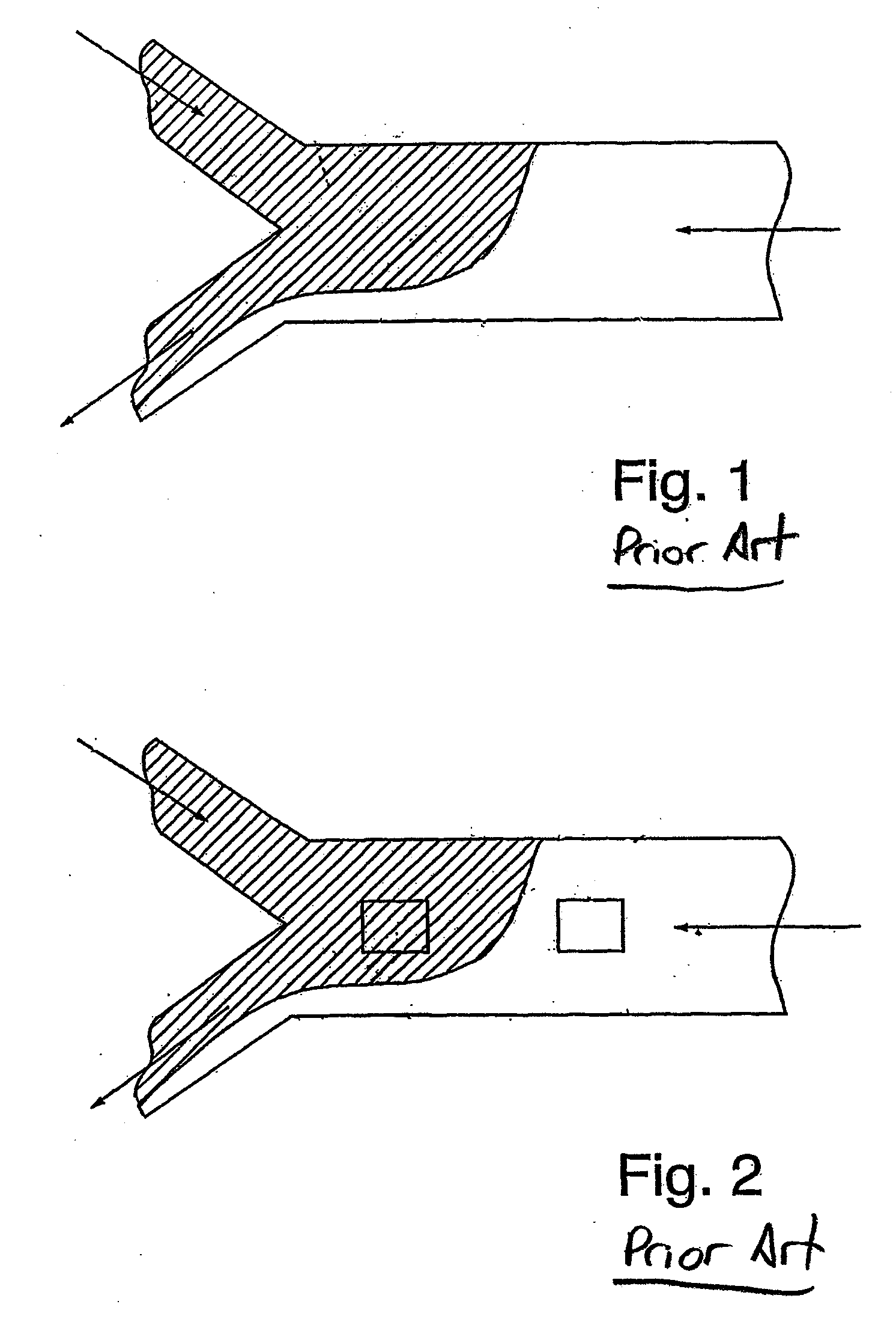
[0047]In the flow cell 100 shown in FIGS. 5-10, the fluid delivery surface 104 is designed such that two main inlet ports 112 are positioned at one end of the fluid delivery surface 104, and a single outlet, or main exhaust port 114 is positioned at the opposing end of the fluid delivery surface 104. During operation of the flow cell 100, continuously flowing guide fluid streams enter the cell through the main inlet ports 112 and, in most instances of operations, will exit the cell 100 through the main exhaust port 114. This design ensures that all fluids entering the cell 100 will flow in a direction from the end of the flow cell 100 where the main inlet ports 112 are located towards the end of the flow cell 100 where the main exhaust port 114 is located. When describing its position within the flow cell 100, the exhaust port 114 is said to be located downstream of the main inlet ports 112. Additionally, the number of inlet ports 112 and outlet ports 114 can be altered as desired, ...

third embodiment

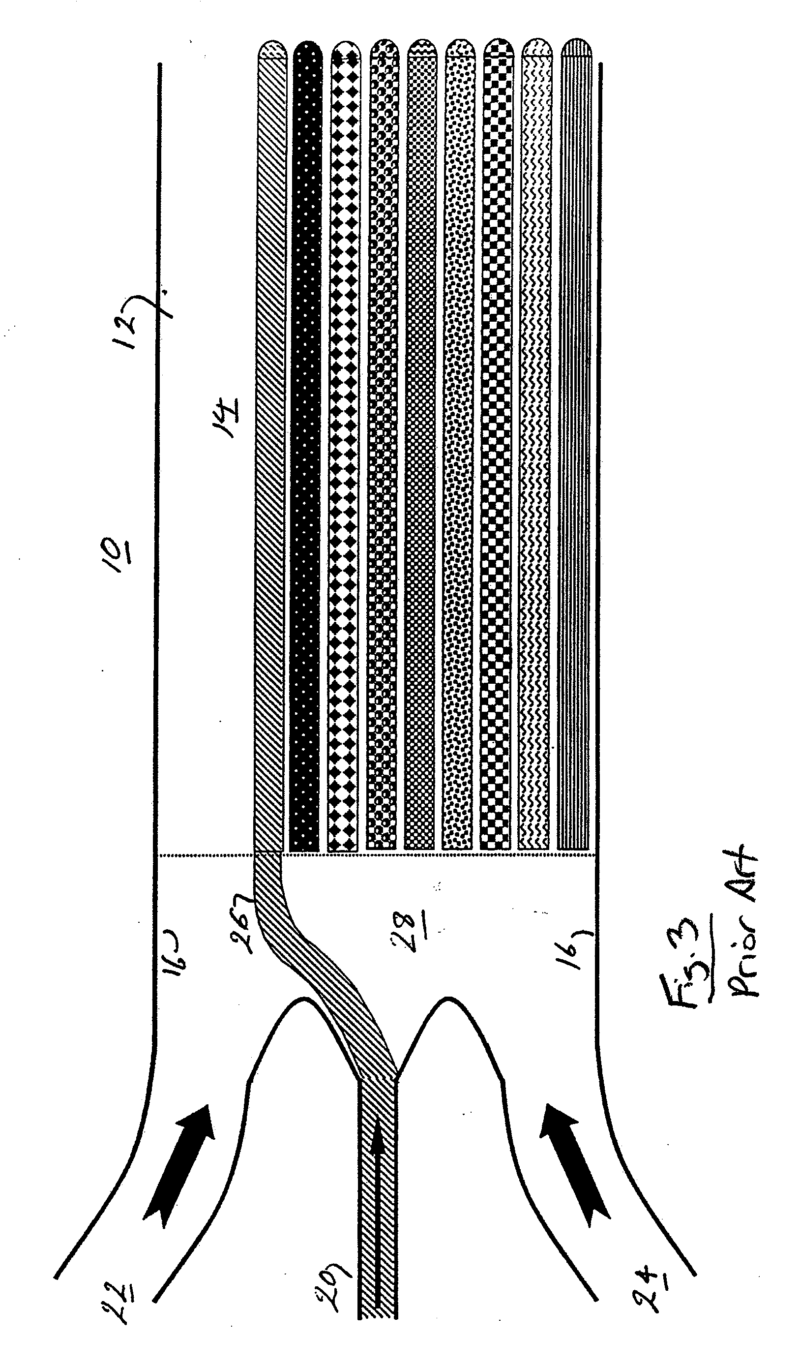
[0069]Looking now at FIG. 18, the flow cell 1000 of the present invention is illustrated in which the flow cell 1000 is capable of location specific addressing of sample fluid streams over a two (2) dimensional sensor spot array 1050 formed in the flow cell 1000. The flow cell 1000 includes sensor spots 1010 oriented in a grid-like pattern 1040 to form an array 1050, similarly to the flow cell 200, with a corresponding set of fluid ports 1008, i.e., fluid inlets 1012, fluid outlet 1014, RIPs 1018 and REPs 1022, 1026, oriented along each column of the spot array 1050. However, the flow cell 1000 also includes an additional set of fluid ports 1008′ disposed along each row of the spot array 1050 and oriented generally perpendicular to the set of fluid ports 1008 disposed along the columns of the array 1050. The various apertures forming the row sets 1008′, i.e., the fluid inlets 1012′, fluid outlet 1014′, RIPs 1018′, and REPs 1022′, 1026′, function identically to the corresponding memb...


PUM

PropertyMeasurementUnit
volumesaaaaaaaaaa
transparentaaaaaaaaaa
volumesaaaaaaaaaa

Abstract

The present invention is a flow cell and method for use in microfluidic analyses that presents highly discrete and small volumes of fluid to isolated locations on a two-dimensional surface contained within an open fluidic chamber defined by the flow cell that has physical dimensions such that laminar style flow occurs for fluids flowing through the chamber. This process of location specific fluid addressing within the flow cell is facilitated by combining components of hydrodynamic focusing with site specific cell evacuation. The process does not require the use of physical barriers within the flow cell or mechanical valves to control the paths of fluid movement.

Description

FIELD OF THE INVENTION[0001]The present invention relates to microfluidic devices, and more particularly to such devices that are used in the analytical analysis of fluid samples that include a detection device.BACKGROUND OF THE INVENTION[0002]In the process of analytical analysis of fluid samples (biologic samples, chemicals reagents, and gases) it is common for test samples to be passed through a chamber containing either a detection substrate, or a transparent window allowing the interrogation of the sample by some form of energy or light. It is common for sample fluids to be delivered and removed from these “detection chambers” using a continuous flow of transport fluid entering the chamber from one end and exiting the chamber at another. Thus these chambers are termed detection “flow cells”, and the analysis techniques that utilize them are termed “flow based” detection methods. During flow based analysis, sample fluids to be tested are delivered as discrete volumes, or ‘plugs’...

Claims


Application Information

Patent Timeline
Patent Type & Authority Applications(United States)
IPC IPC(8): G01N33/00B01J19/00
CPCB01L3/5025B01L3/502761B01L2200/0636B01L2200/141B01L2300/0816B01L2300/0819Y10T436/25B01L2300/0877Y10T436/118339Y10T436/2575Y10T436/117497Y10T436/11B01L2300/0874
Inventor WHALEN, CHRISTOPHER D.
Owner BRUKER DALTONIK GMBH & CO KG
Why Eureka
Try Eureka