Vehicular collision sensing system

a collision sensing and vehicle technology, applied in the direction of pedestrian/occupant safety arrangement, process and machine control, instruments, etc., can solve the problems of large vehicle deceleration, less and consequent risk of injury to vehicle occupants, so as to reduce the chance of driver and/or passenger injury in frontal impa

Inactive Publication Date: 2008-10-30
DELPHI TECH INC
View PDF7 Cites 10 Cited by
  • Summary
  • Abstract
  • Description
  • Claims
  • Application Information

AI Technical Summary

Benefits of technology

[0008]A crash sensing system for determining a vehicle impact includes an electronic controller for activating impact mitigation equipment during both a first stage event and second stage event. The first stage event partially inflates an air bag and / or activates a seatbelt pretensioner and a second stage event fully inflates an air bag. One or more sensors are used for determining the magnitude of both frontal and side impact forces during the vehicle impact. The controller operates to adjust the sensitivity of the sensors based upon vehicle speed measurements. The electronic controller activates equipment to mitigate injuries in frontal impact and side impact collisions.

Problems solved by technology

Generally, the sooner the sensor system recognizes a collision and deploys the restraint, the lesser the chance of driver and / or passenger injury.
Striking a heavy object (such as another vehicle) at a given speed may produce a large vehicle deceleration with consequent risk of injury to vehicle occupants, but striking a light object (such as a traffic barrel) at the same speed would produce an insignificant deceleration with little or no risk to the occupants.
Hence, the use of vehicle speed alone is generally insufficient to determine if the impact will produce significant occupant injuries requiring restraint.
This additional dimension of dual stage airbags can make sensing calibrations difficult.
Calibrating a sensing algorithm to properly deploy dual stage airbags for offset deformable barrier (ODB) and angle crashes can result in tradeoffs with the dual stage calibrations for full frontal threshold-airbag-desired crashes.
Adjusting second stage thresholds for timely deployments for ODB and angle-type crashes can often lead to a calibration that is too sensitive for full frontal impacts, where the result is an unwanted second stage deployments for lower vehicle speed full frontal crashes.

Method used


Image

  • Vehicular collision sensing system
  • Vehicular collision sensing system
  • Vehicular collision sensing system

Examples


Embodiment Construction

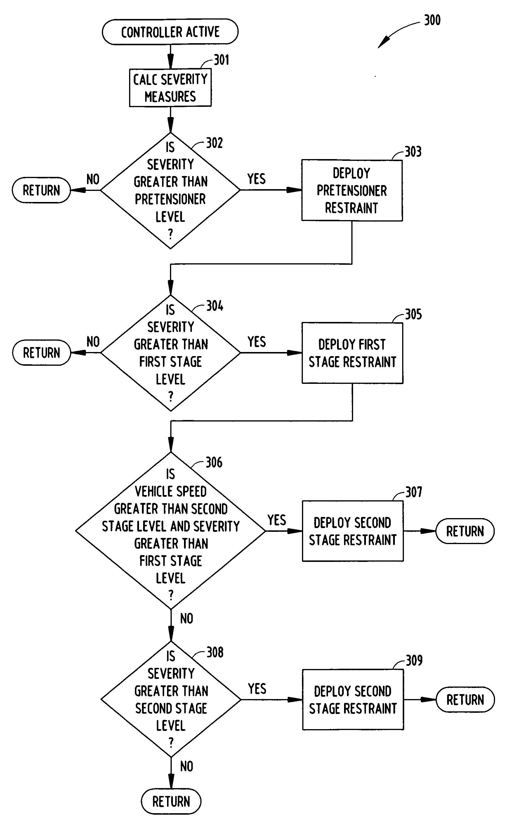
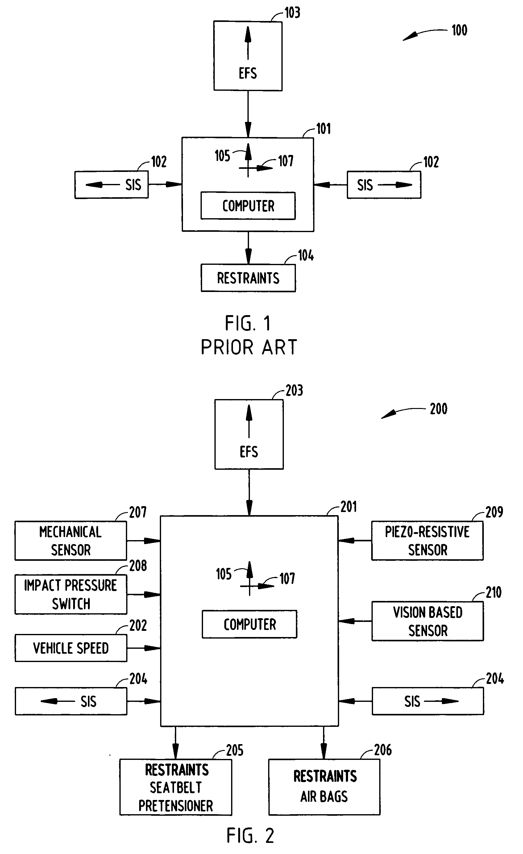
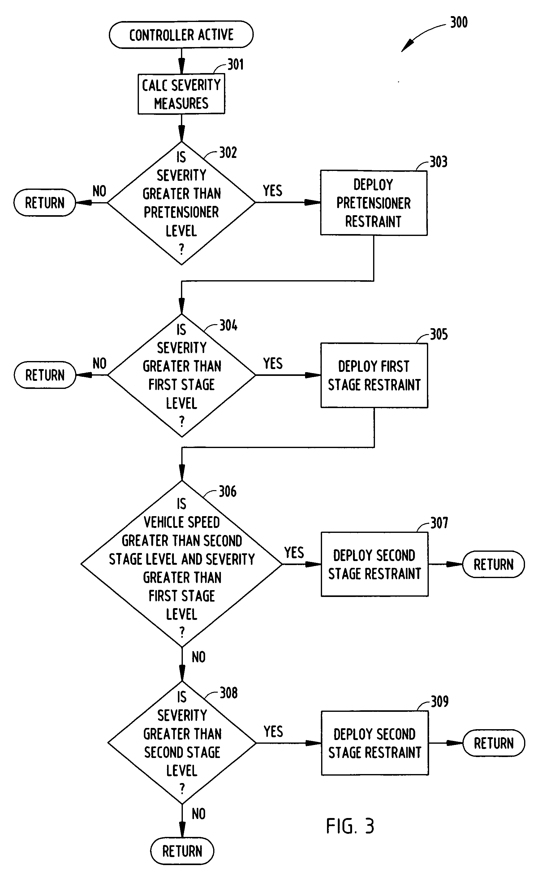
[0016]Before describing in detail embodiments that are in accordance with the present invention, it should be observed that the embodiments reside primarily in combinations of method steps and apparatus components related to an improved vehicular collision sensing system. Accordingly, the apparatus components and method steps have been represented where appropriate by conventional symbols in the drawings, showing only those specific details that are pertinent to understanding the embodiments of the present invention so as not to obscure the disclosure with details that will be readily apparent to those of ordinary skill in the art having the benefit of the description herein.

[0017]In this document, relational terms such as first and second, top and bottom, and the like may be used solely to distinguish one entity or action from another entity or action without necessarily requiring or implying any actual such relationship or order between such entities or actions. The terms “compris...


PUM


Abstract

A crash sensing system for determining a vehicle impact includes an electronic controller for activating impact mitigation equipment during both a first stage event and a second stage event. One or more sensors are used for determining the magnitude of both frontal and side impact forces during the vehicle impact. The controller operates to adjust the sensitivity of the sensors based upon vehicle speed measurements.

Description

CROSS-REFERENCE TO RELATED APPLICATIONS[0001]This application claims the benefit under 35 U.S.C. §119(e) of U.S. Provisional Patent Application Ser. No. 60 / 926,341 filed on Apr. 26, 2007, and assigned to Delphi Technologies, Inc.TECHNICAL FIELD[0002]The present invention relates generally to deployable vehicle restraining systems and more particularly to a sensing system enhancement for use with dual stage airbags.BACKGROUND OF THE INVENTION[0003]Deployable restraints have been used for many years to mitigate occupant injuries in vehicle crashes. These restraints operate by detecting a collision and inflating one or more air bags that act to prevent the driver and / or passenger from contacting the steering wheel or dashboard. Because of the time required to deploy most restraints, the sensor system must be able to predict the deployment of the restraint well in advance of the time it is actually used by the occupant. Generally, the sooner the sensor system recognizes a collision and ...

Claims


Application Information

Patent Timeline
Patent Type & Authority Applications(United States)
IPC IPC(8): G06F19/00
CPCB60R21/0132B60R21/0136B60R2021/0004B60R2021/0006B60R2021/01027B60R2021/01322B60R21/0133
Inventor SIMPSON, RUSSELL L.NICHOLS, DAVID J.LITTLE, DAVID R.
Owner DELPHI TECH INC
Why Eureka
Try Eureka