Coke Oven Doors Having Heating Function

a technology of oven doors and coke ovens, which is applied in the direction of coke oven doors/closures, coke oven heating, retorts, etc., can solve the problems of hot coke pushed out of coke ovens, poor quality coke generated near the coke ovens at both ends, and low yield of good quality blast furnace coke, etc., to achieve easy maintenance control

Inactive Publication Date: 2008-11-06
YAMASAKI IND CO LTD
View PDF3 Cites 70 Cited by
  • Summary
  • Abstract
  • Description
  • Claims
  • Application Information

AI Technical Summary

Benefits of technology

[0017]The present invention provides a coke oven door equipped with a system that sends necessary amount of air to burn coke oven gas that flows through slits of metal shield bars into said hollow space of said metallic door plug under simple actions and prevents excess air supply that causes temperature drop in the bottom-less combustion space and excess oxidation of coke in front of said hollow metallic door plug. Also the present invention provides very easy maintenance control for the system. Tar mist and said solid particles suspende

Problems solved by technology

Hot coke pushed out from coke oven includes poor quality coke generated in the vicinity of both ends of coke oven because of insufficient coking.
This poor quality coke causes low yield of good quality blast furnace coke.
This problem arises from existing refractory door plug, which usually has about 400 mm of thickness and is heated up to a high temperature during coking operation.
When door is put in service again temperature of door plug is lower than before and it causes a delay of coking of coal particles charged in the vicinity of door plug in next coking cycle.
Although this type doors, compared with those existing coke oven door using refractory plug, may have effects to increase coking speed of coal particles charged in the vicinity of coke oven door plug and decrease the generation of poor quality coke, but have not come to industrial use.
Possibly this is because of

Method used


Image

  • Coke Oven Doors Having Heating Function
  • Coke Oven Doors Having Heating Function
  • Coke Oven Doors Having Heating Function

Examples


Embodiment Construction

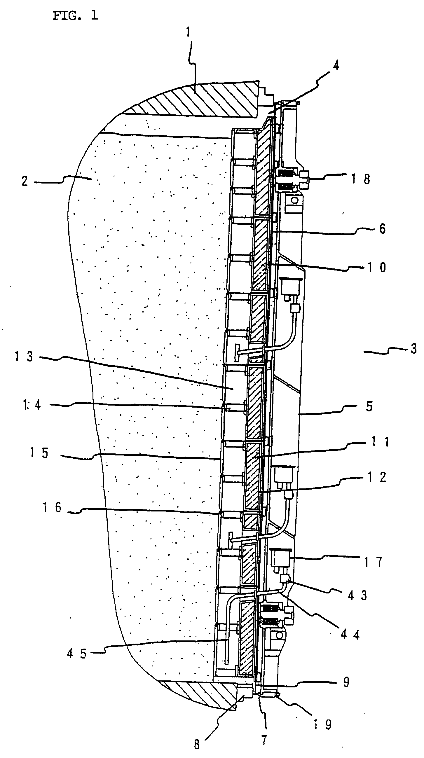
[0028]Details of this invention will be described by reference to the drawings. FIG. 1 is a cross-sectional view in the vicinity of coke oven opening of coke delivery or pushing side illustrating an embodiment of this invention in the direction of oven height. In FIG. 1 reference numeral 1 designates a coke oven, 2 coal particles charged in the coke oven 1. On both sides of coke oven 1 combustion chambers (not shown) are located. They give heat through heating wall to coke oven 1 to produce coke.

[0029]Reference numeral 3 is an oven door structure that opens and closes an opening 4 of coke oven 1. The oven door structure 3 comprises a sturdy cast iron or steel frame 5, slide plate 6 on coke oven side of frame 5, flanges with knife-edge cross section 7 that contact to door jamb 8, seal plate 9 made of heat-resistant metal plate that works as a gas sealing member in conjunction with flanges 7, inner plate 10, heat-insulation box 12 filled with insulating material 11 such as alumina sil...


PUM


Abstract

An air chamber unit provided for a coke oven door enabling to suppress the generation of poor quality coke and reduce tar adhesion to coke oven door by accelerating coking reaction in the vicinity of coke oven door plug. An air chamber unit (17) is installed to control air supply to the bottom-less combustion space provided in hollow metallic coke oven door plug. For the purpose of long lasting stable air supply for said combustion space, air space (20) in the air chamber unit (17) is divided into two sections (A) and (B) by labyrinth partition to give different function for each of those section. Air intake pipe (27) is fitted in section (A) through bottom plate (21) of air chamber unit (17), wherein check valve plate (35) and other related components are provided as air supply control segments. Air supply pipe (30) or air delivery cup having one or more air inlet holes in upper portion is fitted in section (B) through bottom plate (21) of air chamber unit (17), wherein roles to remove contaminant particles suspended in backward flow gas are provided.

Description

TECHNICAL FIELD[0001]This invention relates to coke oven door implemented by hollow metallic door plug having bottom-less gas combustion space to provide heating function, which accelerates coking reaction of coal particles charged in the vicinity of coke oven door plug, gasifying of tar generated during coking and adhered to door and, at the same time, preventing charged coal particles enter into bottom-less combustion space of hollow metallic door plug.BACKGROUND ART[0002]Coke battery manufactures coke by heating coal particles by the heat supplied through heating walls on both sides of coking chamber of coke oven. Hot coke pushed out from coke oven includes poor quality coke generated in the vicinity of both ends of coke oven because of insufficient coking. This poor quality coke causes low yield of good quality blast furnace coke. This problem arises from existing refractory door plug, which usually has about 400 mm of thickness and is heated up to a high temperature during coki...

Claims


Application Information

Patent Timeline
IPC IPC(8): C10B25/06
CPCC10B25/06C10B21/10
Inventor YAMASAKI, KESAO
Owner YAMASAKI IND CO LTD
Why Eureka
Try Eureka