Vacuum wire tensioner for wire bonder

a vacuum wire tensioner and wire tensioner technology, which is applied in the direction of soldering apparatus, manufacturing tools,auxillary welding devices, etc., can solve the problems of high volume of compressed, disturbance of whipping, and impose torque, so as to reduce the introduction of contaminants into the wire tensioner and avoid the need for frequent cleaning of the wire tensioner

a vacuum wire tensioner and wire tensioner technology, which is applied in the direction of soldering apparatus, manufacturing tools,auxillary welding devices, etc., can solve the problems of high volume of compressed, disturbance of whipping, and impose torque, so as to reduce the introduction of contaminants into the wire tensioner and avoid the need for frequent cleaning of the wire tensioner

US20080272178A1Active Publication Date: 2008-11-06ASMPT SINGAPORE PTE LTD

Image

  • Vacuum wire tensioner for wire bonder
  • Vacuum wire tensioner for wire bonder
  • Vacuum wire tensioner for wire bonder

Examples


Embodiment Construction

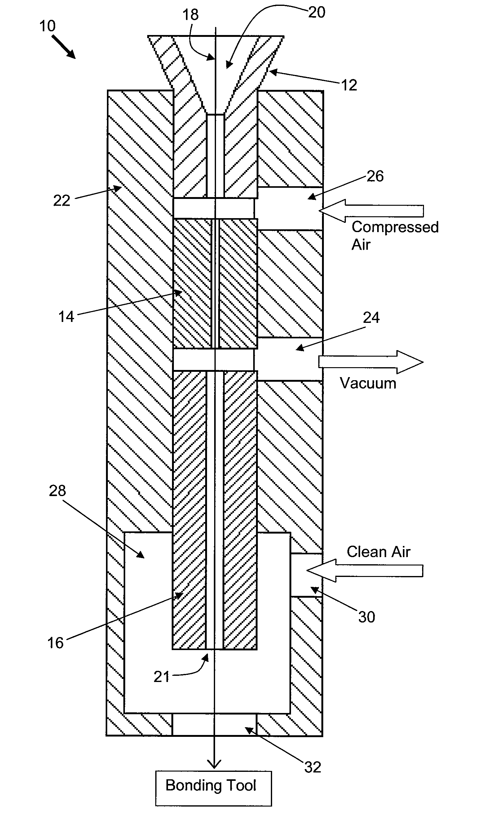
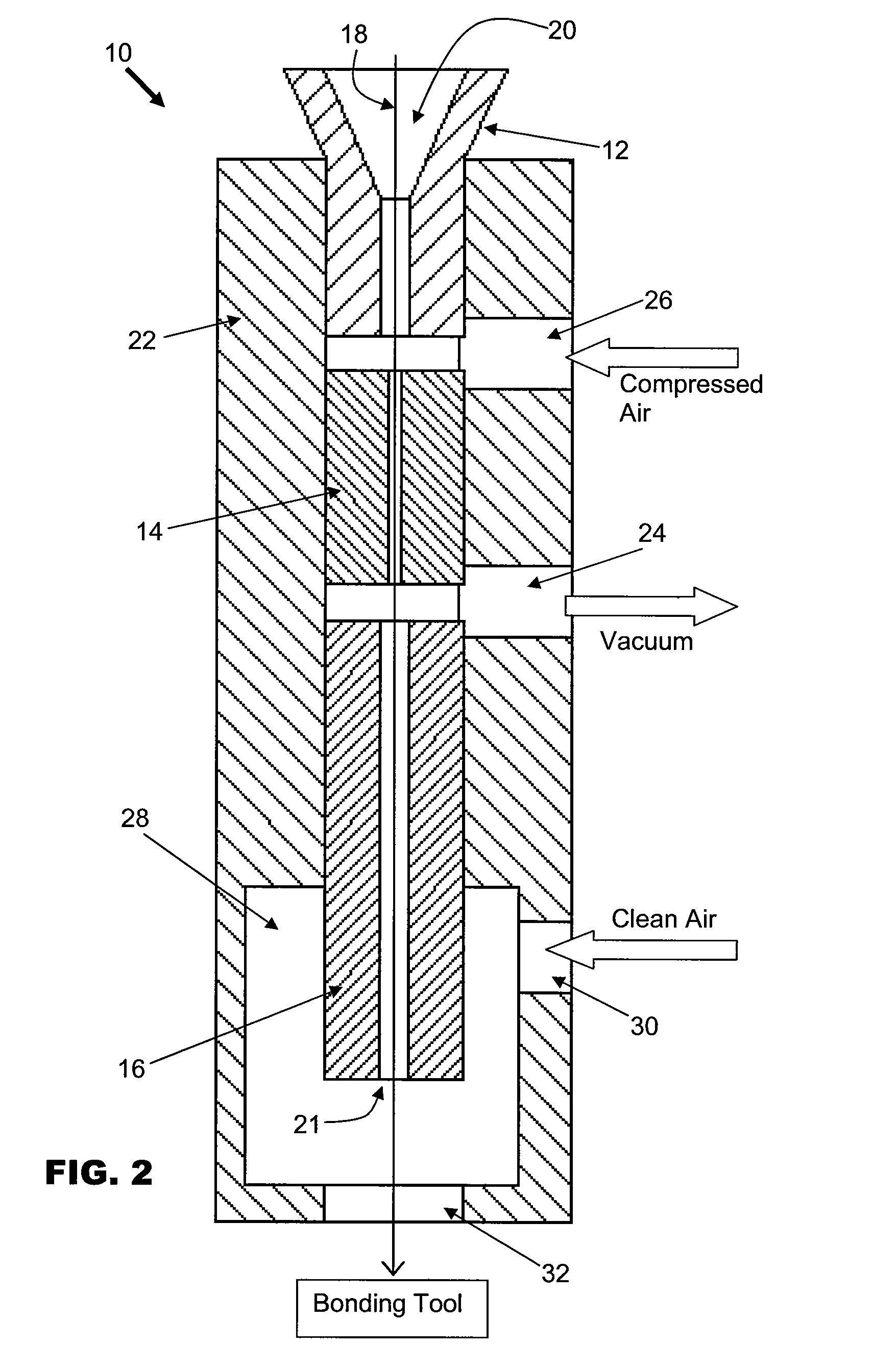
[0017]FIG. 2 is a schematic cross-sectional view of a vacuum wire tensioner according to the preferred embodiment of the invention. The wire tensioner 10 comprises a tubular body through which bonding wire is receivable, the tubular body including a wire inlet 12, inner tube 14 and wire outlet 16. The tubular body has a central bore 18 extending through the respective wire inlet 12, inner tube 14 and wire outlet 16. Bonding wire 20, such as gold wire, is led through the central bore 18 from the wire inlet 12 to the wire outlet 16. The bonding wire 20 is extended from a bore outlet 21 located at an end of the wire outlet 16 portion of the tubular body towards a capillary (not shown) of a bonding tool. The wire inlet 12, inner tube 14 and wire outlet 16 are substantially enclosed by a wire tensioner housing 22, which also serves as a means to secure the wire tensioner 10 to a wire bonding apparatus by securing the housing 22.

[0018]Near a mid-point of the wire tensioner housing 22, a v...


PUM

PropertyMeasurementUnit
Volumeaaaaaaaaaa
Widthaaaaaaaaaa
Widthaaaaaaaaaa

Abstract

A wire tensioner is provided for a wire bonder, the wire tensioner comprising a tubular body having a bore through which bonding wire is receivable and a bore outlet at an end of the tubular body from which the bonding wire is extendable towards a bonding tool. A chamber is formed next to the bore outlet that substantially encloses the bore outlet, the chamber including an air inlet connected to it that is operative to introduce clean air into the chamber. A vacuum outlet is connected to a side of the tubular body and is in fluid communication with the chamber via the bore, the vacuum outlet being operative to draw air from the bore outlet through the bore whereby to pull the wire.

Description

FIELD OF THE INVENTION[0001]The invention relates to a wire bonding apparatus for making wire connections between electronic devices, and in particular, to a wire tensioner for controlling the feeding of wire in such wire bonding apparatus.BACKGROUND AND PRIOR ART[0002]In a wire bonding process, electrically conductive wires are bonded between electrical bonding pads found on semiconductor devices, such as between a semiconductor die and a substrate onto which the die is attached. The substrate is usually a semiconductor leadframe. The electrical connection could also be made between bonding pads found on separate semiconductor dice. The bond is formed by a bonding tool which may be in the form of a capillary attached to an ultrasonic transducer for generating ultrasonic energy to the capillary tip.[0003]Wire is continually fed to the capillary in order to make wire connections. The wire feeding system may comprise a clamp that is operative to secure the wire relative to the bonding...

Claims


Application Information

Patent Timeline
06 Nov 2008
Publication
US20080272178A1
IPC
B23K37/00
CPC
B23K20/004; H01L24/45; H01L24/85; H01L2224/45144; H01L2224/78302; H01L2224/851; H01L2924/01005; H01L2924/01079
Inventors
KWAN, KA SHING KENNY; ZHANG, YUE