Hybrid Power Supply System

a hybrid power supply and power supply technology, applied in valve housings, process and machine control, instruments, etc., can solve the problems of increasing manufacturing costs and size, reducing the power efficiency of the conventional system to about 70%, and inconvenient and inefficient, so as to reduce the size of the hybrid power supply system, reduce the noise of the emi, and increase the power supply efficiency

Inactive Publication Date: 2008-11-06
KWON OH YOUNG +1
View PDF5 Cites 68 Cited by
  • Summary
  • Abstract
  • Description
  • Claims
  • Application Information

AI Technical Summary

Benefits of technology

[0016]The power efficiency of the hybrid power supply system according to the present invention is 91%, which is about 21% higher than the conventional power supply system. Since the input portion of the piezoelectric transformer, the input portion of the ferrite transformer, and the output portion of the DC-AC converter circuit are integrated, the hybrid power supply system is reduced in size, there

Problems solved by technology

The conventional power supply system performs conversion between AC and DC at too many stages, thereby causing inconvenience and inefficiency.
This reduces the power efficiency of the conventional system to about 70% and increases the manufacturing costs and size thereof.
In addition, a conventional ferrite step-down transformer (not shown) used in the DC-AC inverter 3 is not only combustible but also causes Electromagnetic Interference (EMI) noise.
However, the Rosen type piezoelectric transformer has a low power transmission capacity, and its known maximum power is only 10 W.
This piezoelectric transformer is referred to as a “Transoner”, which has a high powe

Method used


Image

  • Hybrid Power Supply System
  • Hybrid Power Supply System
  • Hybrid Power Supply System

Examples


embodiment 1

[0034]FIG. 6 is a circuit diagram of a first embodiment of the present invention.

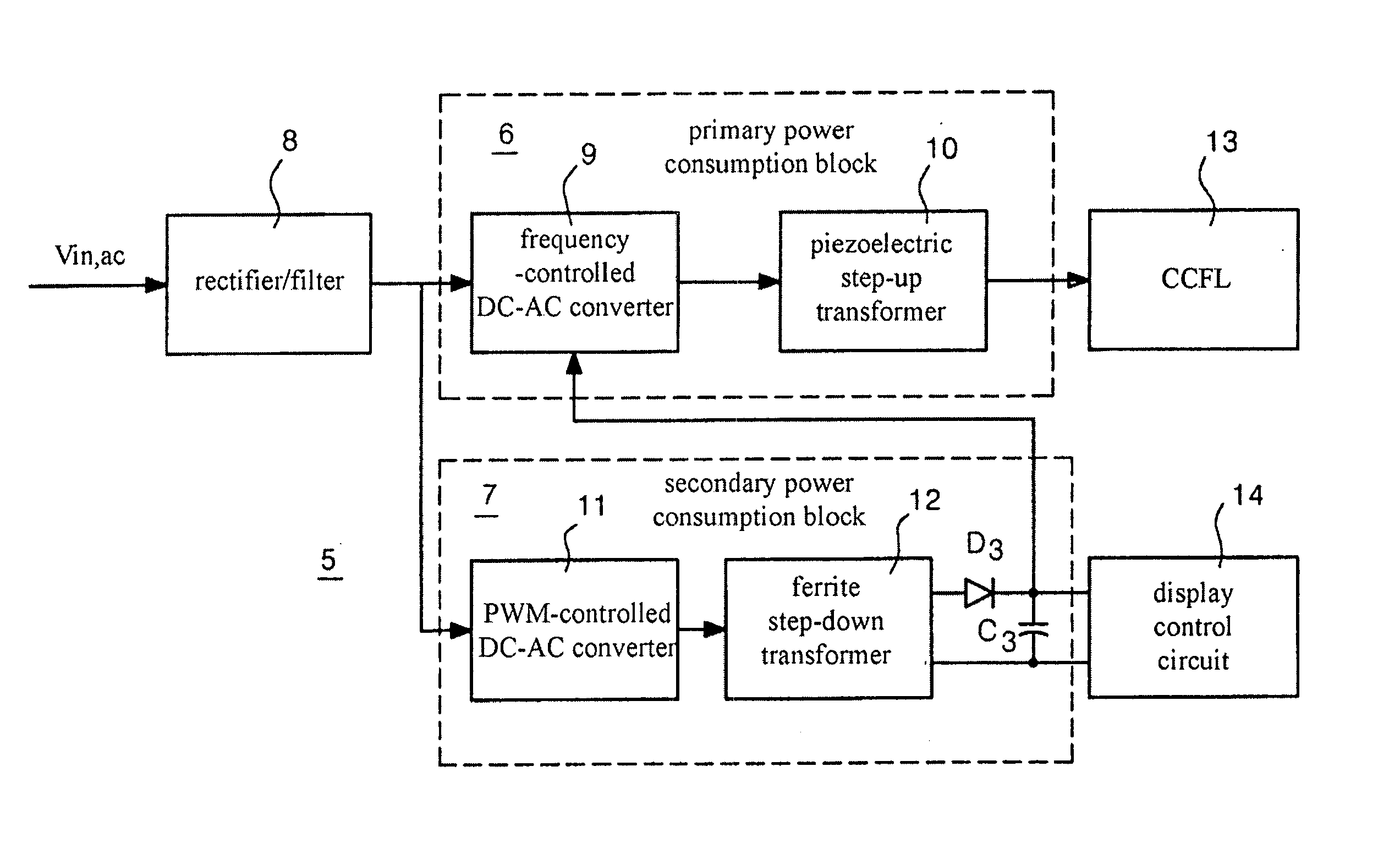
[0035]In this embodiment, a sampler 22 and a comparator 23 are provided for automatic feedback control of the brightness of the CCFL 13. The sampler 22 generates a sampling voltage from an AC current of a CCFL 13 and the comparator 23 compares the sampling voltage with a predetermined reference voltage and generates a feedback output voltage. In this embodiment, a half-bridge MOSFET switch 17 is used as a frequency-controlled DC-AC converter 9.

[0036]First, an input voltage Vin is input to a rectifier / filter 8 including a filter 15 and a rectifier 16, through which the input voltage Vin is filtered and rectified. When the input voltage Vin is 90-132VAC, the rectifier / filter 8 outputs a DC voltage of 120-190VDC, and, when the input voltage Vin is 180-264VAC, it outputs a DC voltage of 250-380VDC.

[0037]The DC-AC converter 9 including the half-bridge MOSFET switch 17 converts the DC voltage output from the ...

embodiment 2

[0042]FIG. 7 is a circuit diagram of a second embodiment of the present invention.

[0043]In this embodiment, primary terminals of a piezoelectric step-up transformer 10 and a ferrite step-down transformer 12 are connected in parallel to an output terminal of a half-bridge MOSFET switch 17, so that DC-AC conversion is eliminated from a secondary power consumption block 7, thereby increasing the power supply efficiency. Since power consumption of each of a display control circuit 14, a VCO 19, and a comparator 23 is low, buck regulators 24 and 25 are used to reduce and stabilize a DC voltage that is input to these circuits.

[0044]An input terminal of the ferrite step-down transformer 12 is connected to an output terminal of the half-bridge MOSFET switch 17. An AC voltage stepped down by the ferrite step-down transformer 12 is converted to a DC voltage through a rectifier circuit D3 and C3. The DC voltage is further stepped down and stabilized through the buck regulator 25, and it is the...

embodiment 3

[0045]FIG. 3 is a circuit diagram of a third embodiment of the present invention.

[0046]In this embodiment, primary terminals of a piezoelectric step-up transformer 10 and a ferrite step-down transformer 12 are connected in series to an output terminal of a half-bridge MOSFET switch 17, so that DC-AC conversion is eliminated from a secondary power consumption block 7, thereby increasing the power supply efficiency. Similar to the second embodiment, since power consumption of each of a display control circuit 14, a VCO 19, and a comparator 23 is low, buck regulators 24 and 25 are used to reduce and stabilize a DC voltage that is input to these circuits.

[0047]Specifically, an input terminal of the ferrite step-down transformer 12 is connected between an output terminal of the half-bridge MOSFET switch 17 and an input terminal of the piezoelectric step-up transformer 10. Accordingly, this embodiment does not require the energy-saving inductance L1 provided in the first and second embodi...


PUM


Abstract

A hybrid power supply system including piezoelectric and ferrite transformers for driving a discharge lamp is provided. Specifically, the hybrid power supply system includes a rectifier/filter, a piezoelectric inverter, and a ferrite converter. The rectifier/filter has an input terminal connected to an external AC voltage to convert the external AC voltage to a DC voltage. The piezoelectric inverter is connected to the rectifier/filter to step up and convert the DC voltage to an AC voltage for driving the discharge lamp. The ferrite transformer is connected to the rectifier/filter to step down the DC voltage to a rated DC voltage for driving discharge lamp circuits other than the discharge lamp. The piezoelectric inverter and the ferrite converter are integrated by connecting a primary side of the piezoelectric step-up transformer and a primary side of the ferrite step-down transformer in series or in parallel with an output terminal of switching circuits.

Description

TECHNICAL FIELD[0001]The present invention relates to a power supply system, and more particularly to a hybrid power supply system including a ferrite transformer and a piezoelectric transformer suitable for a variety of input / output voltages, wherein a converter circuit having an inverter and a rectifier and filter circuit are integrated to decrease the size of the power supply system and increase the power efficiency thereof.BACKGROUND ART[0002]Household power generally has a voltage of 85-264VAC. A Cold Cathode Fluorescent Lamp (CCFL), which is used as a discharge lamp for a backlight of a general LCD monitor, requires a voltage much higher than the household voltage. On the other hand, all display circuits of the general LCD monitor such as a video control circuit, other than the CCFL, use a DC voltage lower than the household voltage. For example, multi-lamp LCD monitors require a rated voltage of 12-15VDC, whereas CCFLs require a voltage higher than about 1,000VAC for lighting...

Claims


Application Information

Patent Timeline
IPC IPC(8): H05B37/02H02M5/40
CPCH05B41/2827H05B41/2828F16K3/0227F16K3/314F16K27/04
Inventor KWON, OH-YOUNGGOLOVTCHANSKI, ALEXANDRE
Owner KWON OH YOUNG
Why Eureka
Try Eureka