
X-Ray Device with Scattered-Beam Suppression

Inactive Publication Date: 2008-11-06
SIEMENS HEALTHCARE GMBH
View PDF6 Cites 1 Cited by
  • Summary
  • Abstract
  • Description
  • Claims
  • Application Information

AI Technical Summary

Benefits of technology

[0005]The present embodiments may obviate one or more of the limitations or drawbacks inherent in the related art. For example, in one embodiment, an X-ray apparatus having a simple, operationally reliable construction can achieve an effective reduction in scattered radiation.
[0013]The scattered-beam component can be reduced by up to 50% with the half-scanning method. This half-scanning method is suitable whenever large proportions of scattered radiation occur, or with large-area X-ray detectors or with small spacing between the focal point and the detector, as in a C-arch device, for example. Under some circumstances, because of the low proportions of scattered radiation in a half-scanning method, the matrix can be left out entirely, which additionally increases the primary radiation at the detector inlet. In contrast to conventional scanning methods, the half-scanning method does not need a mechanical screen system on the side toward the patient. The half-scanning method is distinguished by a simple mechanism. Suppressing the scattered radiation makes it possible to improve the image quality. If these improvements in image quality are used with a goal of reducing the patient dose, then a considerable increase in the radiation output by a factor of 2 is furthermore unnecessary.

Problems solved by technology

The disadvantage of such a scanning method is generally a reduction in the capacity of the X-ray tube, since a large proportion of the radiation generated must be blanked out.
The reduction in radiation output of the X-ray tube must be compensated for by reducing the prefiltration, by a higher voltage, or by longer exposure times, which leads to poorer monochromotization of the beam or blurs from motion.
The mechanical construction is relatively complex and vulnerable, since two screen systems in front of and behind the patient have to be shifted synchronously.

Method used


Image

  • X-Ray Device with Scattered-Beam Suppression
  • X-Ray Device with Scattered-Beam Suppression

Examples


Embodiment Construction

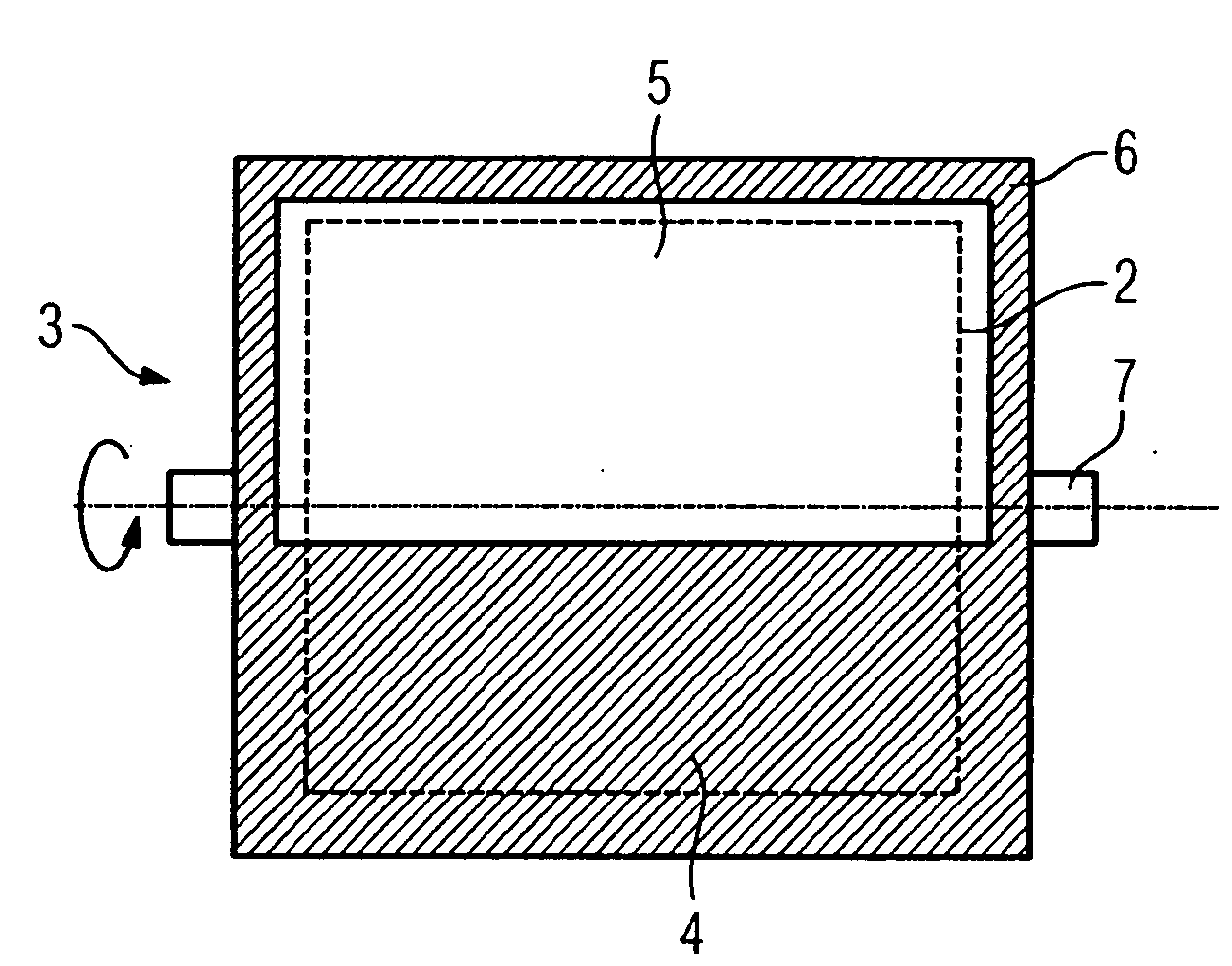
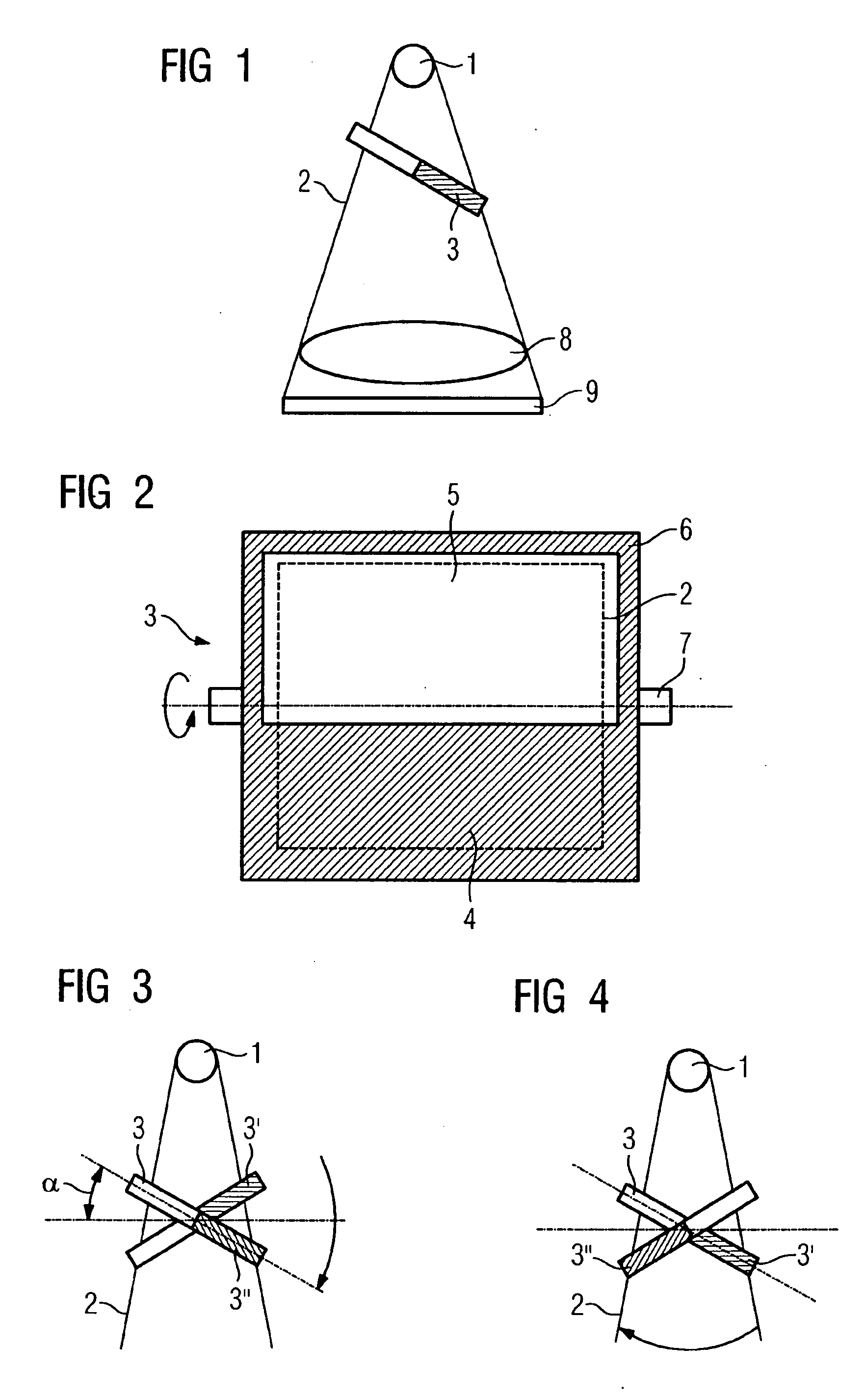
[0017]FIG. 1 shows the schematic construction of an X-ray device, with an X-radiation source 1. A rectangular rotating small plate 3 is located in a radiation cone 2 of the X-radiation source 1. The small plate 3 is located as close as possible to the radiation source 1 so that it need not be embodied as overly large. One half 4 of the small plate 3 has X-ray-absorbing material, while the other half 5, in the exemplary embodiment shown, has only a frame 6, which does not affect the beam path or has limited affect on the beam path of the radiation cone 2. The frame 6 balances the concentric rotation of the small plate 3. A rotary shaft 7 is located at a short spacing from the X-ray-absorbing material on that half 4 of the small plate 3. In the time within which the plate 3 with its absorbent side covers half of the beam path, that half of the image can be recorded. After a half-rotation, the X-ray absorbent side covers the other half of the image, and the second half of the image can...


PUM


Abstract

The invention relates to an X-ray device with an X-ray radiation source and with a preferably digital detector, which is placed in the beam path of the radiation source behind the object, particularly behind a patient. Scattered-rays are suppressed by means of a scanning device that scans the object and the detector only in sections. During a half-scanning process, the X-ray image is composed of half images, one image half being faded out.

Description

[0001]The present patent document is a §371 continuation of PCT Application Serial Number PCT / EP2005 / 056466, filed Dec. 12, 2005, designating the United States. This patent document also claims the benefit of DE 10 2004 060 582.3, filed Dec. 16, 2004.BACKGROUND[0002]The present embodiments relate to an X-ray device with scattered-beam suppression.[0003]X-radiation has been used in medical imaging. The X-rays are generated at a virtually punctate source. After passage through the patient, the attenuated radiation is recorded in a detector. Scattered radiation is created in the patient. Scattered radiation generates a background on the images. Scattered radiation makes noise in the X-ray images because of the quantum nature of X-ray photons.[0004]This kind of scattered radiation can be suppressed with the aid of scanning methods in which only a small area of the detector is exposed directly to radiation at any time. This area is quickly shifted within one pulse over the entire detecto...

Claims


Application Information

Patent Timeline
IPC IPC(8): G21K1/04
CPCA61B6/06A61B6/5282G01N23/04
Inventor BERNHARDT, PHILIPP
Owner SIEMENS HEALTHCARE GMBH
Features
  • Generate Ideas
  • Intellectual Property
  • Life Sciences
  • Materials
  • Tech Scout
  • Unparalleled Data Quality
  • Higher Quality Content
  • 60% Fewer Hallucinations
Learn More