Mold Device and Method of Manufacturing Cylinder Block

Inactive Publication Date: 2008-11-06
HONDA MOTOR CO LTD
View PDF2 Cites 9 Cited by
  • Summary
  • Abstract
  • Description
  • Claims
  • Application Information

AI Technical Summary

Benefits of technology

[0006]The present invention has been made in view of the above drawbacks. It is an object of the present invention to provide a die apparatus having a split core assembly for forming a columnar hole in a casting, the die apparatus being capable of smoothly releasing the split core assembly without the need for a draft angle thereby to form a columnar hole, and a method of manufacturing a cylinder block with the die apparatus.
[0007]Another object of the present invention is to provide a die apparatus for preventing blowholes from developing on or near a surface of a casting when the surface of the casting is cut, thereby allowing the casting to be properly processed by a hard coating process and a heating process, and a method of manufacturing a cylinder block with the die apparatus.

Problems solved by technology

Therefore, if a large amount of material is machined off the casting, then many blowholes are liable to appear in the cut surface of the casting.
However, if the columnar hole is deep, then though the side core member is releasable, another core member may not be releasable and needs to have a draft angle.
However, if the casting has a draft angle, then after the inner surface of the casting is cut, blowholes appear on the cut inner surface and may possibly prevent a hard coating process from being properly performed on the inner surface.
When a casting is heated, the surface of the casting may possibly be unduly deformed due to blowholes that are present on or near the surface of the casting.

Method used


Image

  • Mold Device and Method of Manufacturing Cylinder Block
  • Mold Device and Method of Manufacturing Cylinder Block
  • Mold Device and Method of Manufacturing Cylinder Block

Examples


Embodiment Construction

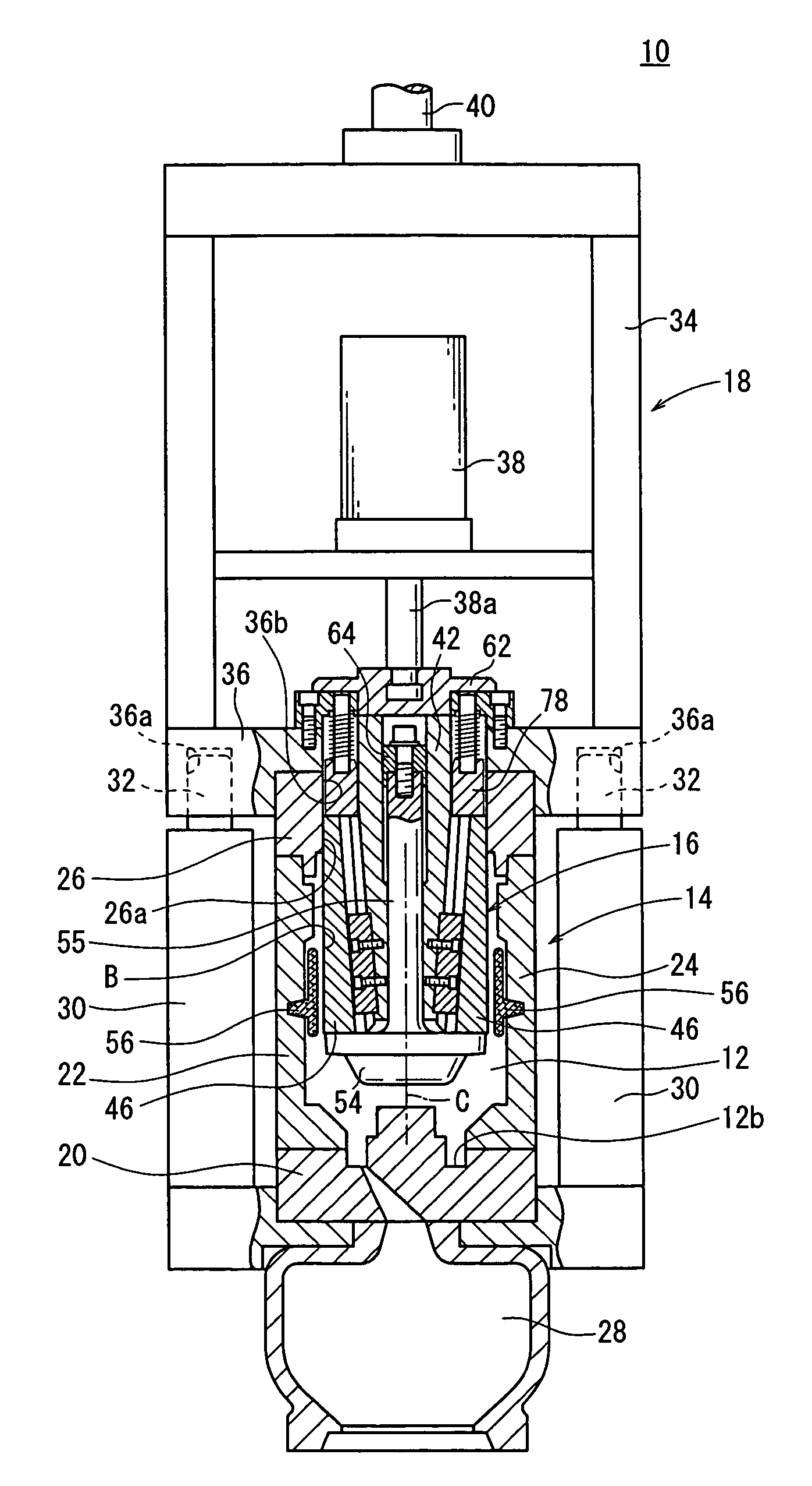
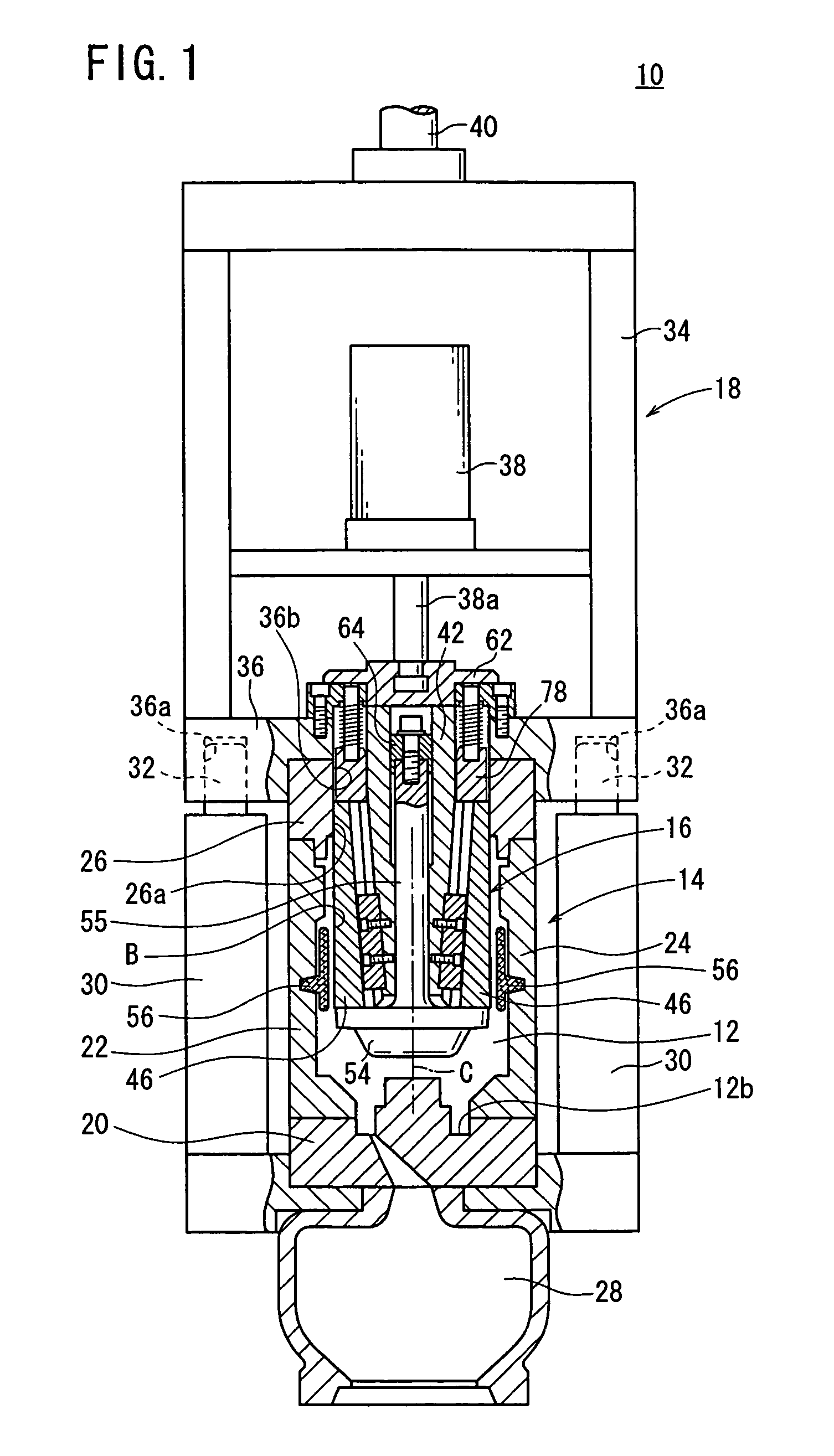
[0038]A die apparatus and a method of manufacturing a cylinder block according to an embodiment of the present invention will be described below with reference to FIGS. 1 through 14 of the accompanying drawings. The method of manufacturing a cylinder block according to the embodiment of the present invention is a method of casting a cylinder block for a single-cylinder engine. Since the cylinder block is of a structure integral with a cylinder head, it has a bore B in the form of a deep bottomed columnar hole. A die apparatus 10 according to the embodiment of the present invention is used to form the bore B.

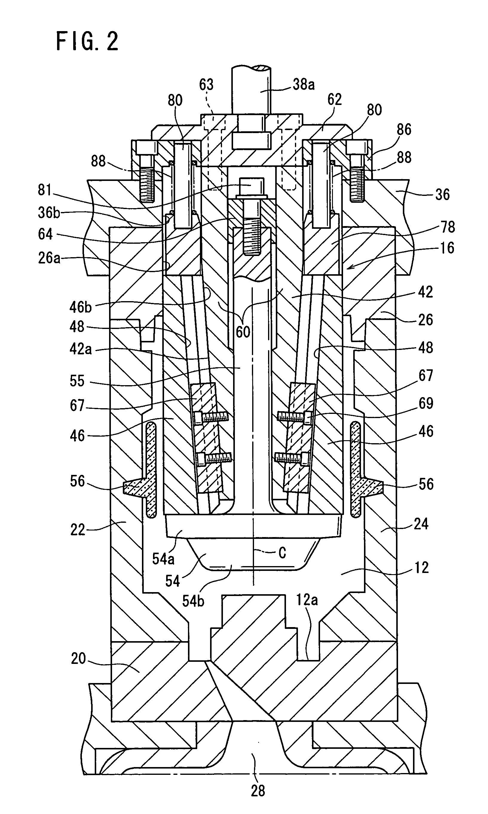
[0039]As shown in FIG. 1, the die apparatus 10 has a die assembly 14 forming an outer circumferential surface of a cavity 12, a split core assembly 16 inserted in the cavity 12, and an actuating mechanism 18 for actuating the split core assembly 16 back and forth.

[0040]The die assembly 14 comprises a fixed die 20 for forming a cylinder head portion of the cylinder block, a first ...


PUM

PropertyMeasurementUnit
Timeaaaaaaaaaa
Angleaaaaaaaaaa
Shapeaaaaaaaaaa

Abstract

A mold device and a method of manufacturing a cylinder block. The mold device comprises a split core having two first split cores formed so that the tip parts thereof may be in a tapering shape, two second split cores installed between the first spilt cores, and an inner core is installed at the center part and pushing out the first split cores in the direction receding from the center axis thereof. When the inner core is pushed out to push out and position the first spilt cores, both end parts of the second split cores are brought into contact with the tip parts of the adjacent first split cores, and the outer side-faces of the first split cores and the outer side-faces of the second split cores form a cylindrical shape. When the inner core is raised, the first split cores and the second split cores are pulled to the axial center by first engagement pieces and second engagement pieces.

Description

TECHNICAL FIELD[0001]The present invention relates to a die apparatus having a split core for forming a columnar hole, and a method of manufacturing a cylinder block with the die apparatus.BACKGROUND ART[0002]For manufacturing a cast product having a columnar hole such as a bore in an engine cylinder block, it is customary to insert a core into a cavity of a casting die, cast a molten metal into the cavity, remove the core after the molten metal is solidified, and release the casting from the die, so that the casting with a columnar hole defined therein is produced. In order to remove the core smoothly, the core needs to have a certain draft angle for removal. However, since the bore has to be of a gradient-free cylindrical shape, it is necessary to cut the casting depending on the draft angle. If the draft angle is large or the columnar hole is deep, then the amount of material machined off the casting is large when the casting is cut, the time required to cut the casting is long, ...

Claims


Application Information

Patent Timeline
IPC IPC(8): B05D3/00B22D29/00B22D45/00B22C9/10B22C9/24F02F1/00
CPCB22C9/103B22C9/24B22D15/02B22D15/04
Inventor SAKURAI, AKIRAMIYASAKA, HAJIMEASAI, YOSHIMICHIOHASHI, HIROYUKINAGAO, KAZUMI
Owner HONDA MOTOR CO LTD
Why Eureka
Try Eureka