Stacks Of Separators And Electrodes Alternately Stacked One On Top Of The Other And Fixed For Li Storage Batteries

a technology of separators and electrodes, which is applied in the direction of secondary cell details, sustainable manufacturing/processing, paper/cardboard containers, etc., can solve the problems of thermal destruction of separators, short circuit between electrodes, and growing potential risk of stored energy being released in an uncontrolled manner

Inactive Publication Date: 2008-11-06
EVONIK DEGUSSA GMBH
View PDF36 Cites 87 Cited by
  • Summary
  • Abstract
  • Description
  • Claims
  • Application Information

AI Technical Summary

Problems solved by technology

With increasing size of the batteries, there is, owing to the larger quantity of stored energy, a growing potential risk that the stored energy will be released in an uncontrolled manner as a result of destruction of the battery.
As a result of the excess gas pressure, voids can form between the individual layers and the individual layers can move relative to one another, with the result that short-circuit can occur between the electrodes.
Polymeric separators may then be thermally destroyed, and complete thermal destruction of the cell may occur.
Moreover, the pocket construction occupies space and gives rise to additional weight since the weld seam is outside the stack.
A disadvantage of this method is that the adhesive has to be applied very exactly to the individual electrodes.
Since, in contrast to other battery types (Pb, NiCd, NiBeH) not water but a flammable solvent, such as, for example, an organic carbonate, is used as a solvent for the electrolytes, the short-circuit often leads to an explosion and as a rule to combustion of the cells.
This can likewise lead to a short-circuit when the pressure declines, since the electrodes do not always slide back into the pockets and may thus come into direct contact with the opposite electrodes.
Furthermore, the process for the production of stacks having pockets is complicated and tedious since the pockets have to be individually welded or adhesively bonded (3 to 7 s hold time) and many different operations have to be carried out alternately (cutting to length, stacking, welding / adhesive bonding, stacking, etc.), i.e. in any case movements of the tools relative to the stack are required (moving parts which can lead to wear).
The handling of the stacks having pockets is also difficult since the layers of pockets and opposite electrodes are not fixed relative to one another.
This can also be achieved to a limited extent if spaces are present between the adhesive bonds.
In this way, it is possible to ensure that as little adhesive as possible penetrates into the area between electrodes and separator, thus preventing the separator area or areas of the active material from becoming blocked with adhesive and thus no longer being available for ion transport.

Method used


Image

  • Stacks Of Separators And Electrodes Alternately Stacked One On Top Of The Other And Fixed For Li Storage Batteries
  • Stacks Of Separators And Electrodes Alternately Stacked One On Top Of The Other And Fixed For Li Storage Batteries
  • Stacks Of Separators And Electrodes Alternately Stacked One On Top Of The Other And Fixed For Li Storage Batteries

Examples


example 1

Stack with Hotmelt Adhesive, Adhesively Bonded Over Lines

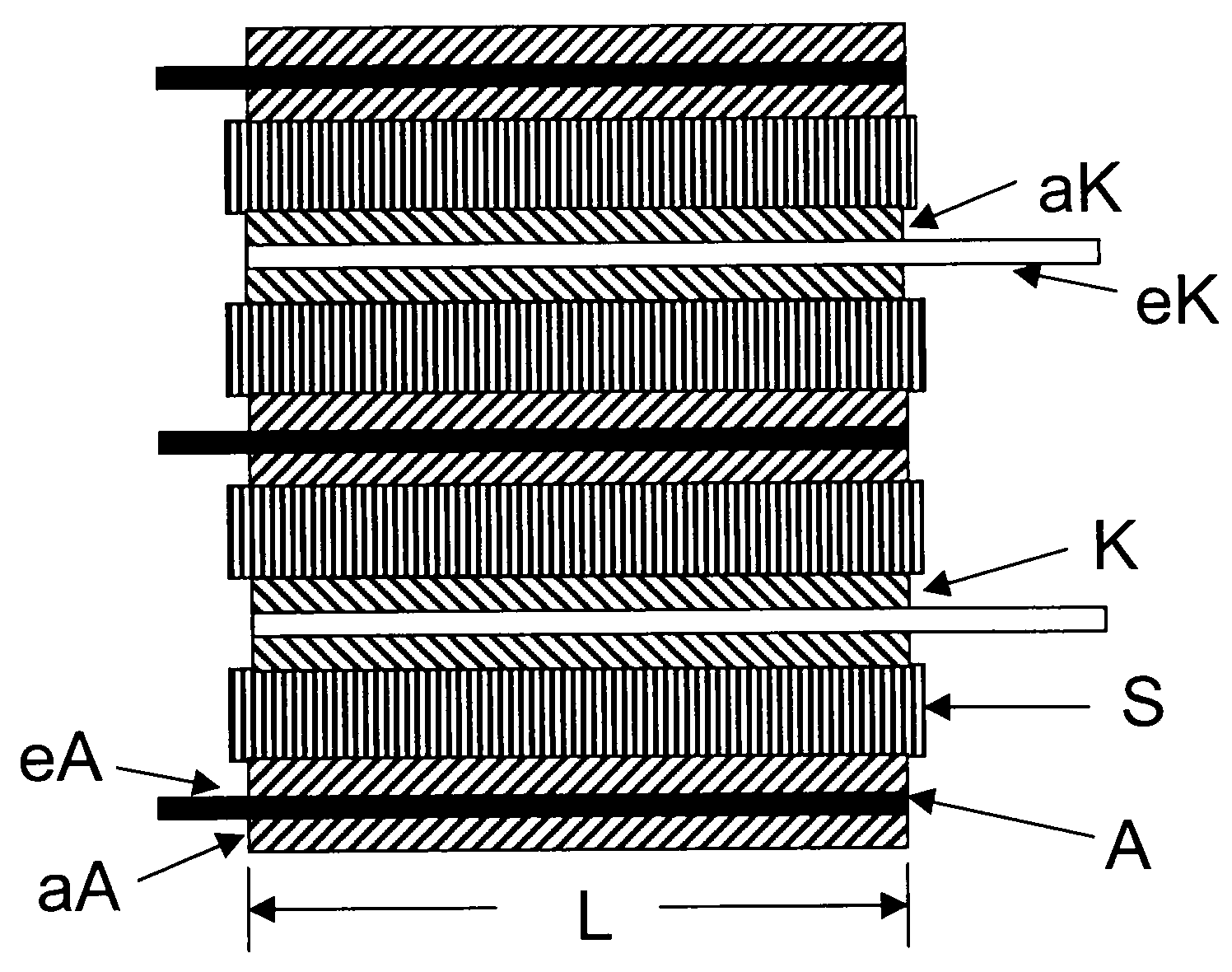
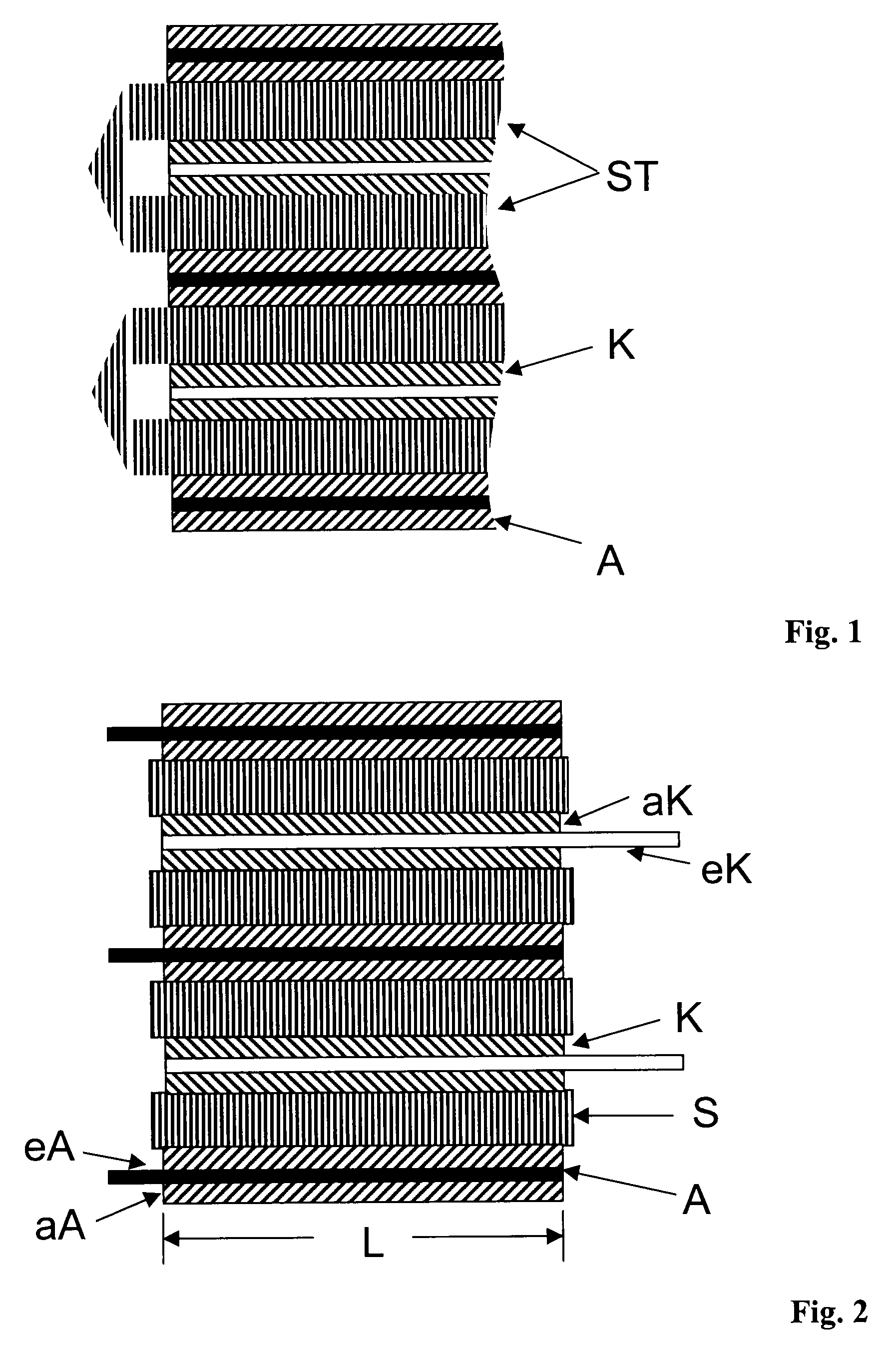
[0071]A separator S240 P25 (Degussa AG, Germany) having the dimensions 72 mm×126 mm is placed on an electrode A (anode) having the dimensions 70 mm×131 mm (including 7 mm Cu edge), according to FIG. 2 (Enax Inc., Japan), so that the separator projects by 1 mm on all sides beyond the electrodes in the region of the copper foil coated with active material. The opposite electrode having the dimensions 65 mm×129 mm (including 9 mm of bare aluminum foil), (cathode; Enax Inc., Japan) is then placed on top, it being necessary to ensure that the separator completely covers on all sides the region of the aluminum foil coated with active material. The electrodes are arranged in such a way that the bare aluminum foils project from the stack beyond the narrow sides of the cathodes on one side of the stack, and the bare copper foils project beyond the narrow sides of the anodes on the opposite side of the stack. Further layers of electrode...

example 2

Stack with UV-Crosslinking Acrylate Adhesive, Adhesively Bonded Over Lines

[0076]A separator S240 P25 having the dimensions 72 mm×126 mm (Degussa AG, Germany) is placed on an electrode A (anode) having the dimensions 70 mm×131 mm (including 7 mm of uncoated copper on the narrow side), according to FIG. 2 (Enax Inc., Japan), so that the separator projects by 1 mm on all sides beyond the electrodes in the region of the copper foil coated with active material. The opposite electrode having the dimensions 65 mm×129 mm (including 9 mm of bare aluminum foil), (cathode; Enax Inc., Japan) is then placed on top, it being necessary to ensure that the separator completely covers on all sides the region of the aluminum foil coated with active material. The electrodes are arranged in such a way that the bare aluminum foils project from the stack beyond the narrow sides of the cathodes on one side of the stack, and the bare copper foils project beyond the narrow sides of the anodes on the opposite...

example 3

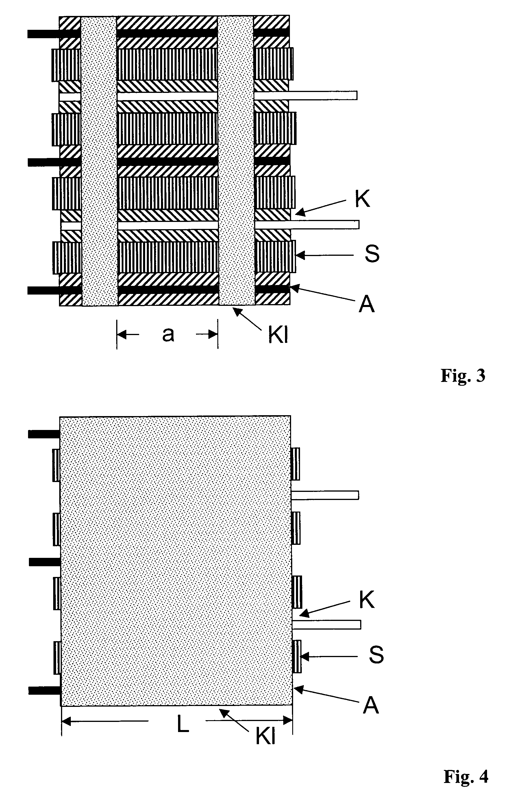
Stack with UV-Crosslinking Acrylate Adhesive, Adhesively Bonded Over the Whole Lateral Area

[0080]A separator S240 P25 (Degussa AG, Germany) having the dimensions 72 mm×126 mm is placed on an electrode A (anode) having the dimensions 70 mm×131 mm (including 7 mm Cu edge), according to FIG. 2 (Enax Inc., Japan), so that the separator projects by 1 mm on all sides beyond the electrodes in the region of the copper foil coated with active material. The opposite electrode having the dimensions 65 mm×129 mm (including 9 mm of bare aluminum foil), (cathode; Enax Inc., Japan) is then placed on top, it being necessary to ensure that the separator completely covers on all sides the region of the aluminum foil coated with active material. The electrodes are arranged in such a way that the bare aluminum foils project from the stack beyond the narrow sides of the cathodes on one side of the stack, and the bare copper foils project beyond the narrow sides of the anodes on the opposite side of the ...


PUM

PropertyMeasurementUnit
widthaaaaaaaaaa
widthaaaaaaaaaa
distanceaaaaaaaaaa

Abstract

The present invention relates to stacks comprising separators and electrodes stacked alternately one on top of the other and fixed, the stack having, on at least one side and/or edge of the stack, at least one adhesive bond comprising an organic adhesive, which bond adhesively bonds the electrodes and separators of the stack to one another, and a method for the production thereof and the use of these stacks in Li batteries.

Description

[0001]The present invention relates to a stack of separators and electrodes stacked alternately one on top of the other and fixed, a method for the production thereof and the use of this stack in Li batteries.PRIOR ART[0002]Lithium ion batteries have a very high energy density, based on volume and weight. For mobile compact applications, such as notebooks, digital cameras and cell phones, virtually exclusively Li batteries are therefore now being used. With increasing size of the batteries, there is, owing to the larger quantity of stored energy, a growing potential risk that the stored energy will be released in an uncontrolled manner as a result of destruction of the battery. For the use of Li batteries, for example in hybrid vehicles, suitable safety mechanisms or devices which prevent uncontrolled release of energy must therefore be present.[0003]For the use of large batteries, the safety of the cells must therefore be as great as possible in order to be able to ensure a high le...

Claims


Application Information

Patent Timeline
Patent Type & Authority Applications(United States)
IPC IPC(8): H01M2/16B32B37/00H01M10/0525H01M10/058H01M10/36
CPCH01M2/08H01M10/02H01M10/0436Y10T156/10H01M10/058Y02E60/122Y02T10/7011H01M10/0525Y02E60/10Y02P70/50H01M10/0585H01M50/46H01M50/461H01M50/463H01M50/434Y02T10/70
Inventor SCHORMANN, ANDREASHENNIGE, VOLKERHOERPEL, GERHARDHYING, CHRISTIANPILGRAM, PETER
Owner EVONIK DEGUSSA GMBH
Why Eureka
Try Eureka