
Retinal Prosthesis with a New Configuration

a retinal prosthesis and configuration technology, applied in the field of neural stimulation, can solve the problems of retinal ischemia and hemorrhage, increase the electrical resistance between the array and the retina, and electric field dispersion, and achieve good sealing with the scleral tissue, increase the electrical resistance, and cut the delicate retinal tissue

Active Publication Date: 2008-11-06
SECOND SIGHT MEDICAL PRODS +1
View PDF11 Cites 49 Cited by
  • Summary
  • Abstract
  • Description
  • Claims
  • Application Information

AI Technical Summary

Benefits of technology

The solution allows for more precise and stable electrical stimulation of retinal cells, reducing tissue damage and enhancing the ability to provide artificial vision without causing mechanical stress, thereby improving the effectiveness of retinal prostheses.

Problems solved by technology

Too little pressure causes increased electrical resistance between the array and retina, along with electric field dispersion.
Too much pressure may block blood flow causing retinal ischemia and hemorrhage.
Pressure on the neural retina may also block axonal flow or cause neuronal atrophy leading to optic atrophy.
Further, the edges of a flexible circuit polymer array may be quite sharp and cut the delicate retinal tissue.

Method used


Image

  • Retinal Prosthesis with a New Configuration
  • Retinal Prosthesis with a New Configuration
  • Retinal Prosthesis with a New Configuration

Examples


Embodiment Construction

[0089]The following description is of the best mode presently contemplated for practicing the invention. This description is not to be taken in a limiting sense, but is made merely for the purpose of describing the general principles of the invention. The scope of the invention should be determined with reference to the claims.

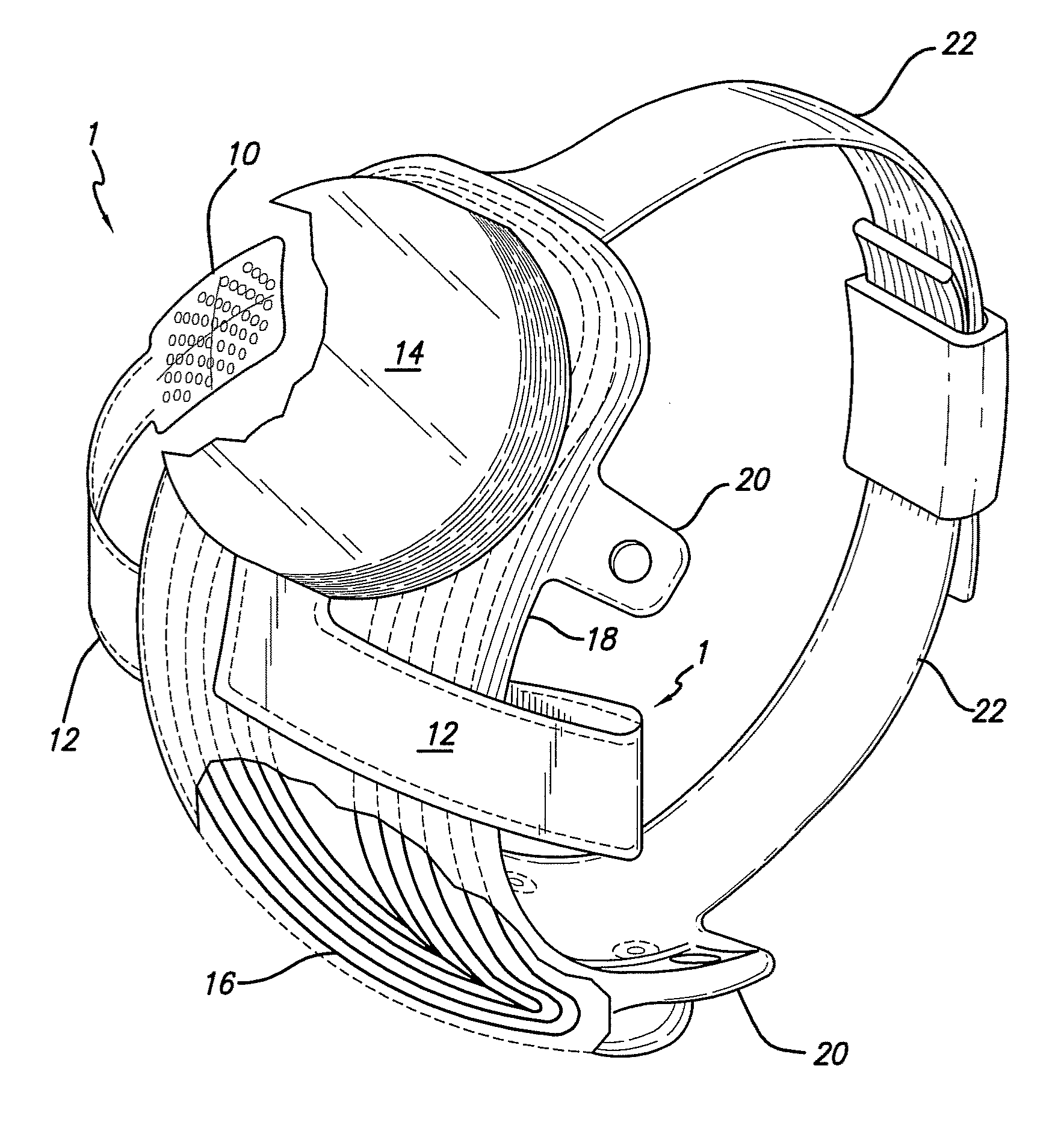
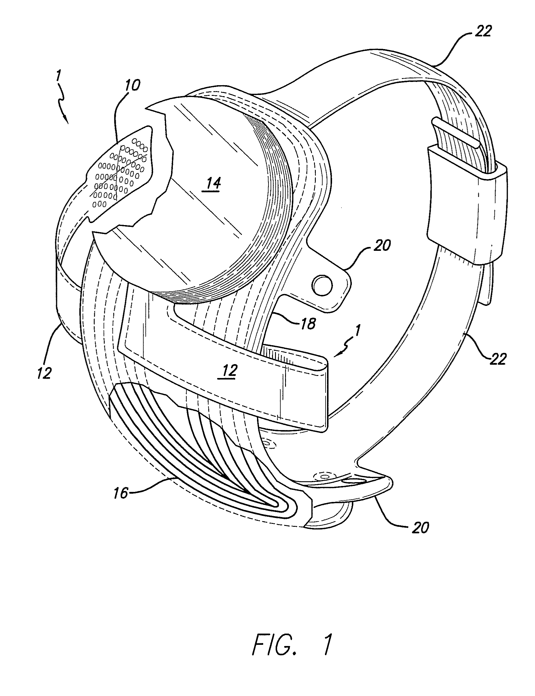
[0090]FIG. 1 shows a perspective view of the implanted portion of the preferred retinal prosthesis. A flexible circuit 1 includes a flexible circuit electrode array 10 which is mounted by a retinal tack (not shown) or similar means to the epiretinal surface. The flexible circuit electrode array 10 is electrically coupled by a flexible circuit cable 12, which pierces the sclera and is electrically coupled to an electronics package 14, external to the sclera.

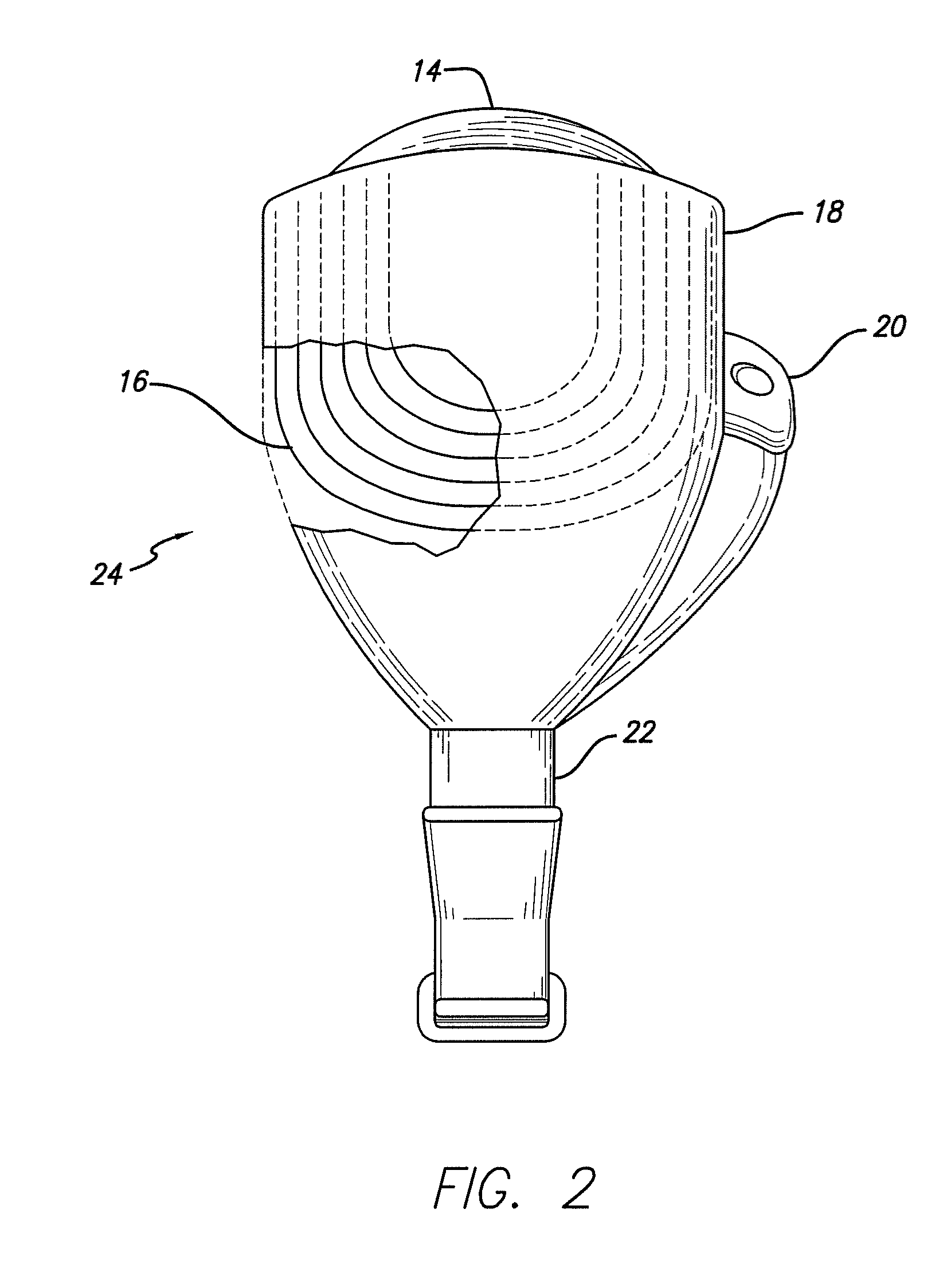
[0091]The electronics package 14 is electrically coupled to a secondary inductive coil 16. Preferably the secondary inductive coil 16 is made from wound wire. Alternatively, the secondary inductive coil 16 m...


PUM

PropertyMeasurementUnit
angleaaaaaaaaaa
angleaaaaaaaaaa
angleaaaaaaaaaa

Abstract

Polymer materials are useful as electrode array bodies for neural stimulation. They are particularly useful for retinal stimulation to create artificial vision, cochlear stimulation to create artificial hearing, and cortical stimulation, and many related purposes. The pressure applied against the retina, or other neural tissue, by an electrode array is critical. Too little pressure causes increased electrical resistance, along with electric field dispersion. Too much pressure may block blood flow. Common flexible circuit fabrication techniques generally require that a flexible circuit electrode array be made flat. Since neural tissue is almost never flat, a flat array will necessarily apply uneven pressure. Further, the edges of a flexible circuit polymer array may be sharp and cut the delicate neural tissue. By applying the right amount of heat to a completed array, a curve can be induced. With a thermoplastic polymer it may be further advantageous to repeatedly heat the flexible circuit in multiple molds, each with a decreasing radius. Further, it is advantageous to add material along the edges. It is further advantageous to provide a fold or twist in the flexible circuit array. Additional material may be added inside and outside the fold to promote a good seal with tissue.

Description

CROSS-REFERENCE TO RELATED APPLICATIONS[0001]This application is a divisional of application Ser. No. 11 / 523,965, entitled “Retinal Prosthesis with a New Configuration”, filed Sep. 19, 2006, which application claims the benefit of U.S. Provisional Application No. 60 / 718,660, entitled “System Architecture and Stimulation Methods for a Retinal Prosthesis”, filed Sep. 19, 2005, the disclosures of which is incorporated herein by reference.[0002]This application claims the benefit of U.S. Provisional Application No. 60 / 718,769, entitled “System for Testing and Configuring a Retinal Prosthesis”, filed Sep. 19, 2005, the disclosures of which is incorporated herein by reference.[0003]This application claims the benefit of U.S. Provisional Application No. 60 / 718,779, “Transretinal Flexible Circuit Electrode Array”, filed Sep. 19, 2005, the disclosures of all which is incorporated herein by reference.[0004]This application claims the benefit of U.S. patent application Ser. No. 11 / 521,281, “Tr...

Claims


Application Information

Patent Timeline
Patent Type & Authority Applications(United States)
IPC IPC(8): A61N1/00
CPCA61N1/0543Y10T29/49158H05K1/028H05K1/0281H05K1/118H05K3/0014H05K3/28H05K2201/0133H05K2201/09018H05K2201/09145H05K2201/09909H05K2201/2009H05K2203/1105H05K2203/1476H05K2203/302A61N1/37223A61N1/36046
Inventor GREENBERG, ROBERT J.MCMAHON, MATTHEW J.LITTLE, JAMES SINGLETONMCCLURE, KELLY H.MECH, BRIAN V.TALBOT, NEIL HAMILTONNEYSMITH, JORDAN M.
Owner SECOND SIGHT MEDICAL PRODS
Learn More