
System, methods, and computer readable media, for product design using coupled computer aided engineering models

a technology of computer aided engineering and product design, applied in the direction of cad techniques, design optimisation/simulation, instruments, etc., can solve the problems of limiting the ability to modify the cae model, laborious, hands-on process, etc., and achieve the effect of reducing the requirement of database and increasing design flexibility

Inactive Publication Date: 2008-11-06
OPTIMAL SOLUTIONS SOFTWARE
View PDF24 Cites 42 Cited by
  • Summary
  • Abstract
  • Description
  • Claims
  • Application Information

AI Technical Summary

Benefits of technology

[0010]Embodiments of the present invention provide systems, methods, and computer readable media for performing product design and analysis. The new methods of product design use CAD and CAE models in combination with FFD by enabling coupled deformation of multiple correlated CAE models configured for analyzing different physical parameters. Additionally, the FFD process may use T-spline meshes to reduce database requirement, increase design flexibility and enable design modifications at a broad range of detail.

Problems solved by technology

One difficult portion of this process is the conversion of the design or CAD model into a CAE model or a “mesh.” CAD and CAE models are fundamentally based on entirely different geometric models.
Creation of a CAE model or mesh from a CAD model is often a laborious, hands-on process.
As a result, currently it may often take hours or days to create an accurate CAE model.
Another less obvious problem with the process is that the ability to modify the CAE model is restricted by the parameters associated with the CAD model.

Method used


Image

  • System, methods, and computer readable media, for product design using coupled computer aided engineering models
  • System, methods, and computer readable media, for product design using coupled computer aided engineering models
  • System, methods, and computer readable media, for product design using coupled computer aided engineering models

Examples


Embodiment Construction

[0030]In the following detailed description, reference is made to the accompanying drawings which form a part hereof, and in which is shown by way of illustration specific embodiments in which the invention may be practiced. These embodiments are described in sufficient detail to enable those of ordinary skill in the art to practice the invention. It should be understood, however, that the detailed description and the specific examples, while indicating examples of embodiments of the invention, are given by way of illustration only and not by way of limitation. From this disclosure, various substitutions, modifications, additions rearrangements, or combinations thereof within the scope of the present invention may be made and will become apparent to those skilled in the art.

[0031]Software processes and analysis methods illustrated herein are intended to illustrate representative processes that may be performed by a general purpose or special purpose processing system. Unless specifi...


PUM


Abstract

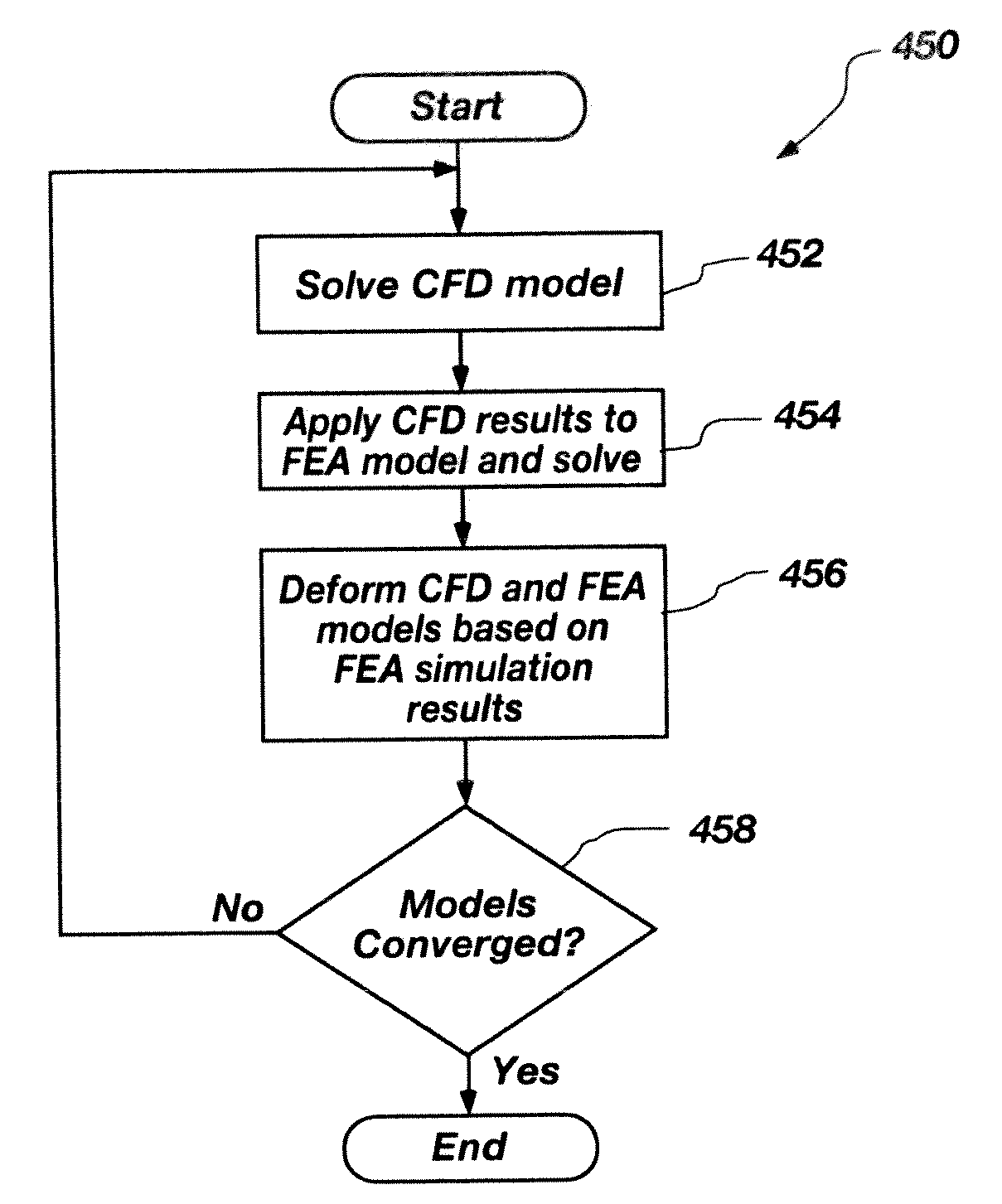
Methods, systems, and computer readable media are used for analyzing a design. A finite element analysis (FEA) model and a correlated computational flow dynamics (CFD) model are defined. A parametric volume is defined with control points forming a mesh bounding a common design object of the models. Control points on the parametric volume are adjusted to develop a design deformation of the FEA model and the CFD model. An analysis loop is performed until a convergence is achieved. The analysis loop includes simulating the CFD model to develop resultant forces and simulating the FEA model with the resultant forces applied to develop resultant displacements. The analysis loop also includes deforming the CFD model and the FEA model to match the resultant displacements by adjusting control points on the parametric volume to generate a corresponding analysis deformation of the FEA model and the CFD model.

Description

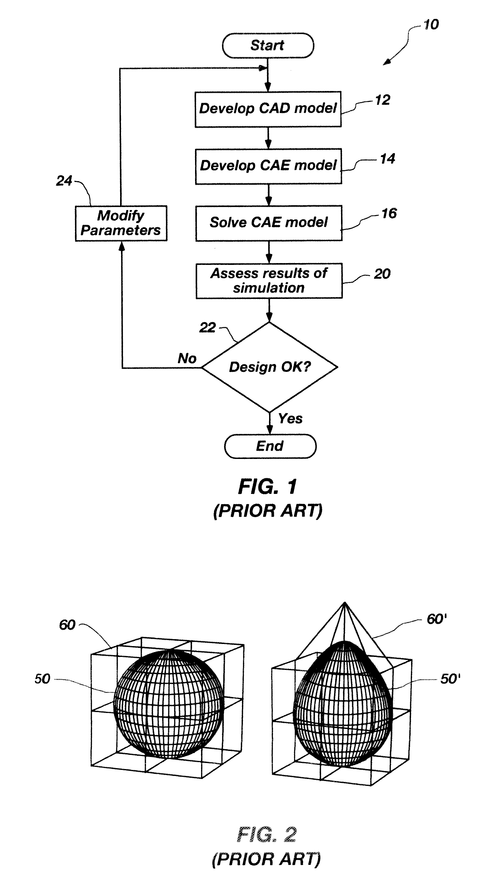
CROSS-REFERENCE TO RELATED APPLICATIONS[0001]This application claims the benefit of U.S. Provisional Patent Application Ser. No. 60 / 918,657 filed Mar. 19, 2007 for SYSTEM AND METHOD FOR PRODUCT DESIGN USING COUPLED-PHYSICS DESIGN DEFORMATION TECHNOLOGY, the disclosure of which is incorporated by reference herein in its entirety.TECHNICAL FIELD[0002]Embodiments of the present invention relate generally to methods for analyzing and designing products, and more specifically for analyzing and adjusting simulation models of product designs. BACKGROUND[0003]Today, engineers often model designs using Computer-Aided Design (CAD) tools and simulations to develop product without having to actually build the product until the engineers have thoroughly analyzed the design. FIG. 1 illustrates a conventional product design process 10.[0004]As part of the design process, a CAD model is created 12. When a design model is ready to analyze, a digital simulation model (also known as a Computer Aided E...

Claims


Application Information

Patent Timeline
Patent Type & Authority Applications(United States)
IPC IPC(8): G06F17/50
CPCG06F17/5018G06F2217/16G06F30/23G06F2111/10
Inventor LANDON, MARK D.
Owner OPTIMAL SOLUTIONS SOFTWARE
Learn More