To crimping system with integrated monitoring

a crimping system and integrated monitoring technology, applied in the direction of pliers, shaping safety devices, electrical equipment, etc., can solve the problems of not being able to detect all, poor positioning, and known crimping systems that cannot avoid defects, so as to facilitate the crimping operation. ensuring the effect of quality control

Inactive Publication Date: 2008-11-13
EUROCOPTER
View PDF7 Cites 32 Cited by
  • Summary
  • Abstract
  • Description
  • Claims
  • Application Information

AI Technical Summary

Benefits of technology

[0013]An object of the invention is to propose a simplified lightweight crimping tool, in particular for facilitating use

Problems solved by technology

Known crimping systems do not make it possible to avoid the defects that might occur, and in particular: i) from using a clamp having a crimping mechanism that, as a result of wear, no longer complies with the required standard for crimping accuracy; ii) from using a positioner that does not correspond to the contact, to the conductor wire, to the clamp, to the set of punches in the clam

Method used


Image

  • To crimping system with integrated monitoring
  • To crimping system with integrated monitoring
  • To crimping system with integrated monitoring

Examples


Embodiment Construction

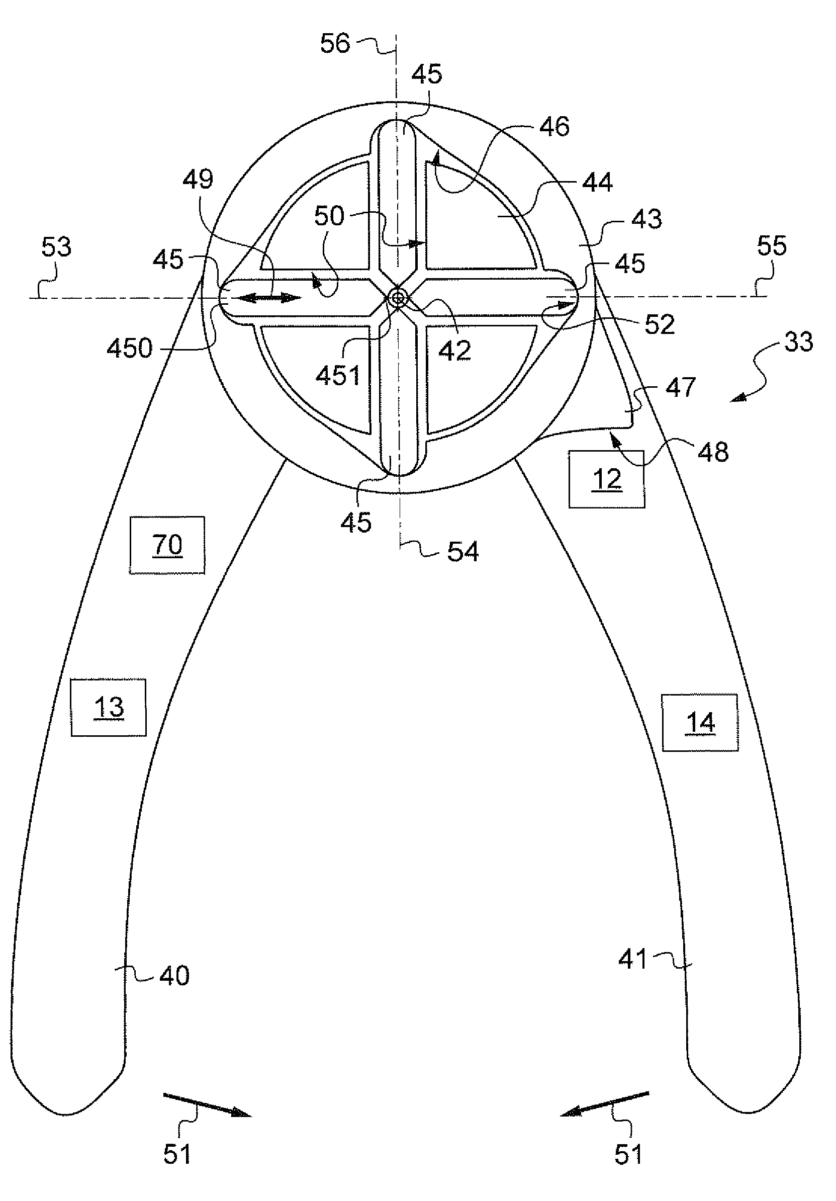
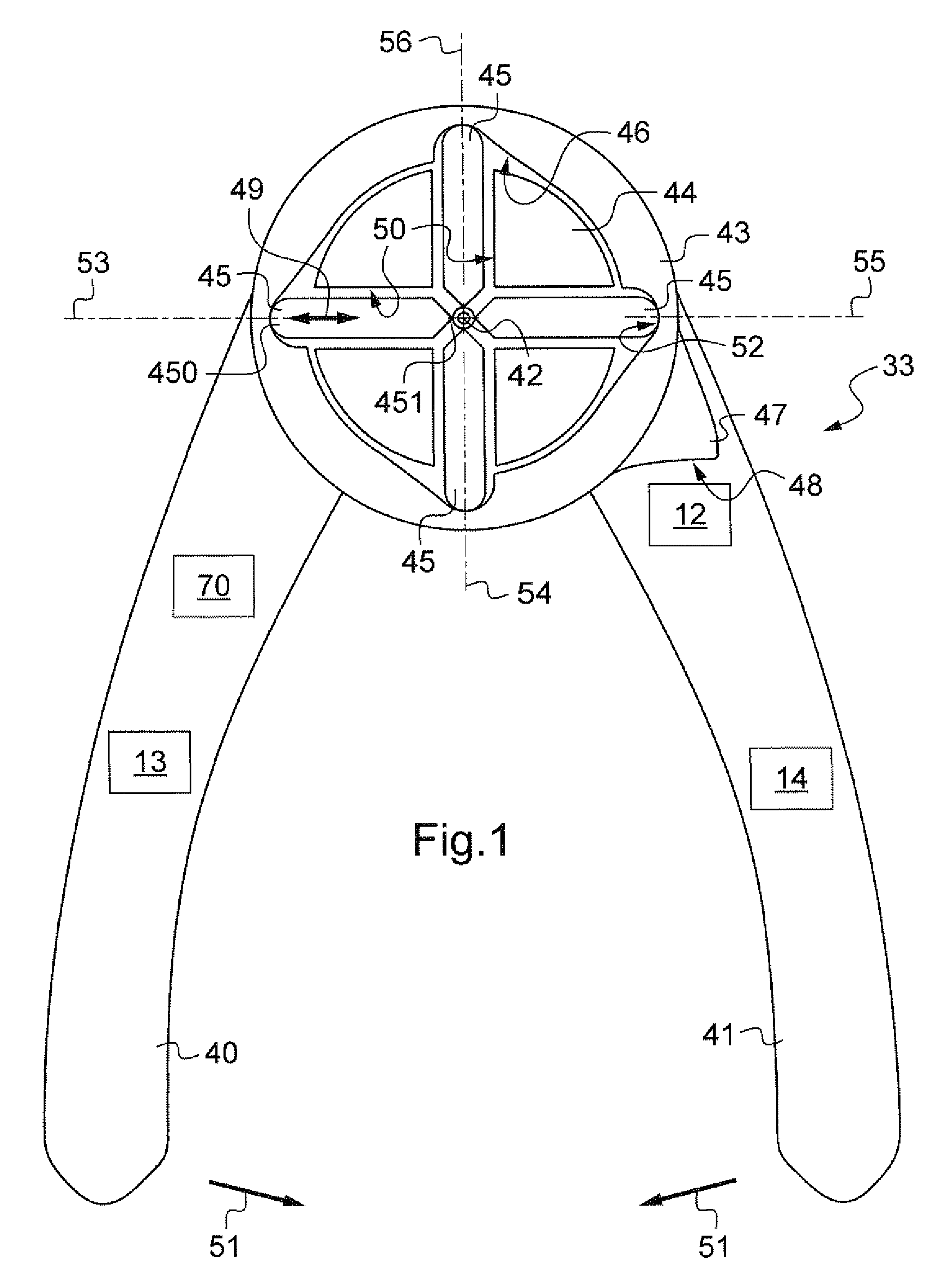
[0030]With reference to FIG. 1, the crimping clamp 33 has two arms or handles 40 and 41 that are mounted to pivot relative to each other about a pivot axis 42 that is perpendicular to the plane of FIG. 1

[0031]The handle 41 is secured to a ring 43 about the axis 42, having an inside face 46 that is cylindrical in shape and that presents a profile that is periodic: the face is formed by four identical portions, each occupying 90° (about the axis 42), and each presenting a recessed portion 52.

[0032]The handle 40 is secured to a part 44 supporting four identical punches 45 received respectively in four housings or channels 50 provided in the part 44 and extending respectively along four coplanar axes 53 to 56 angularly spaced at 90° intervals.

[0033]Each punch has an inner end portion 451 that presents a shape (indentation) adapted to the pin for crimping, and an outer end portion 450 that is designed to slide against the inside face 46, 52 of the ring against which it bears.

[0034]The cl...


PUM


Abstract

A crimping tool including a punch carrier, a plurality of punches movable in translation in radial housings of the punch carrier, a thrust member having an inside face co-operating with the outer ends of the punches, the thrust member being pivotally mounted relative to the punch carrier, such that pivoting of the thrust member causes a contact to be crimped, a tool body having two pivotal handles for causing the thrust member and the punch carrier to pivot mutually, and a member for adjusting the stroke of the punches, a sensor sensitive to the position of the member for adjusting the stroke of the punches, a sensor sensitive to an identity signal from a contact positioning tool, and a memory associated with the position sensor and with the identity sensor and arranged to record the data delivered by the sensors and/or to deliver the data to a data processor unit.

Description

[0001]The present invention relates to a crimping system with integrated monitoring and to a crimping tool for such a system.[0002]The technical field of the invention is that of fabricating crimping tools.BACKGROUND OF THE INVENTION[0003]The present invention relates in particular to a crimping system comprising a crimping clamp and a tool for positioning a contact—a pin or a connector—for crimping to the end of a conductor wire, the crimping clamp and the positioning tool being capable of being releasably (reversibly) secured to each other, as described in particular in patent GB-1 385 426.[0004]The invention applies in particular to such a system in which the clamp is fitted with a force sensor that is sensitive to the crimping force, the system further including a data processor unit connected to the clamp to control it, to deliver thereto signals / data conveying information useful for a crimping operation that is to be performed, and / or for receiving data / signals therefrom conve...

Claims


Application Information

Patent Timeline
IPC IPC(8): B21C51/00
CPCB25B27/10B25B27/146H01R43/0424H01R43/0488
Inventor PACAUD, ALAINTONTIC, PHILIPPE
Owner EUROCOPTER
Why Eureka
Try Eureka