Control method and control apparatus of internal combustion engine

a control method and control apparatus technology, applied in the direction of electrical control, instruments, applications, etc., can solve the problems of poor fuel evaporated status, less combustion, and more instability of combustion

Inactive Publication Date: 2008-11-13
HONDA MOTOR CO LTD
View PDF10 Cites 4 Cited by
  • Summary
  • Abstract
  • Description
  • Claims
  • Application Information

AI Technical Summary

Benefits of technology

[0007]The present invention has been made in consideration of the above situations. It is an object of the present invention to improve the fuel efficiency and the exhaust gas purification performance while reducing the pumping loss in a low-load range or a low and middle-load ranges. It is also an object of the present invention to improve the combustion stability during warming-up stage of an internal combustion engine and to facilitate the warming-up of the internal combustion engine.
[0008]Further, it is also an object of the present invention to improve the fuel efficiency and the exhaust gas purification performance in the vicinity of a predetermined load in a low range or a low and middle-load ranges and to secure the necessary engine output in a high load range. Moreover, it is also an object of the present invention to decrease the pumping loss in the first load range. Furthermore, it is also an object of the present invention to improve the degree of precision of engine output control by the internal EGR rate across a wide range.

Problems solved by technology

Further, during warming-up of an internal combustion engine whose temperature is low, its combustibility is lower than that of the engine which is already warmed up since the temperature in the combustion chamber is also low and thus the evaporated status of fuel is poor.
Therefore, if the internal EGR rate is high, the combustion becomes more unstable such that an accidental fire could easily occur.
Moreover, because the internal EGR is performed to lower the maximum combustion temperature, the warming-up of the internal combustion engine is not promoted.

Method used


Image

  • Control method and control apparatus of internal combustion engine
  • Control method and control apparatus of internal combustion engine
  • Control method and control apparatus of internal combustion engine

Examples


Embodiment Construction

[0047]Hereinafter, preferred embodiments of the present invention will be described with reference to FIGS. 1 to 14(B).

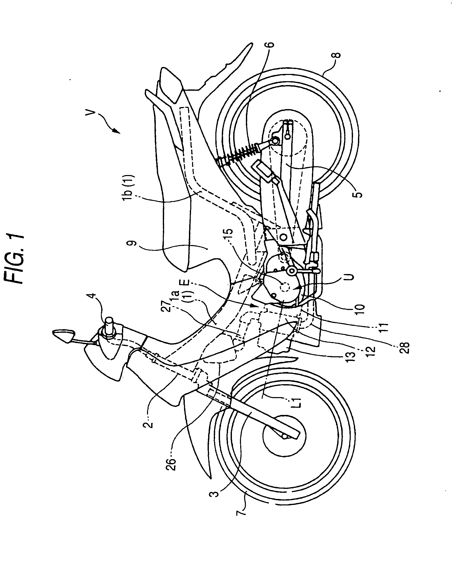
[0048]Referring to FIG. 1, an internal combustion engine E to which the present invention is applied is mounted on a motorcycle V as a vehicle. The motorcycle V comprises a body frame 1 having a front frame 1a and a rear frame 1b; a handle 4 fixed to an upper end of a front fork 3 which is rotatably supported by a head pipe 2 combined with a front end of the front frame 1a; a front wheel 7 rotatably supported by a lower end of the front fork 3; a power unit U supported by the body frame 1; a rear wheel 8 rotatably supported by a rear end of a swing arm 5 which is swingably supported by the body frame 1; a rear cushion 6 connecting the rear frame 1b with a rear portion of the swing arm 5; and a body cover 9 which covers the body frame 1.

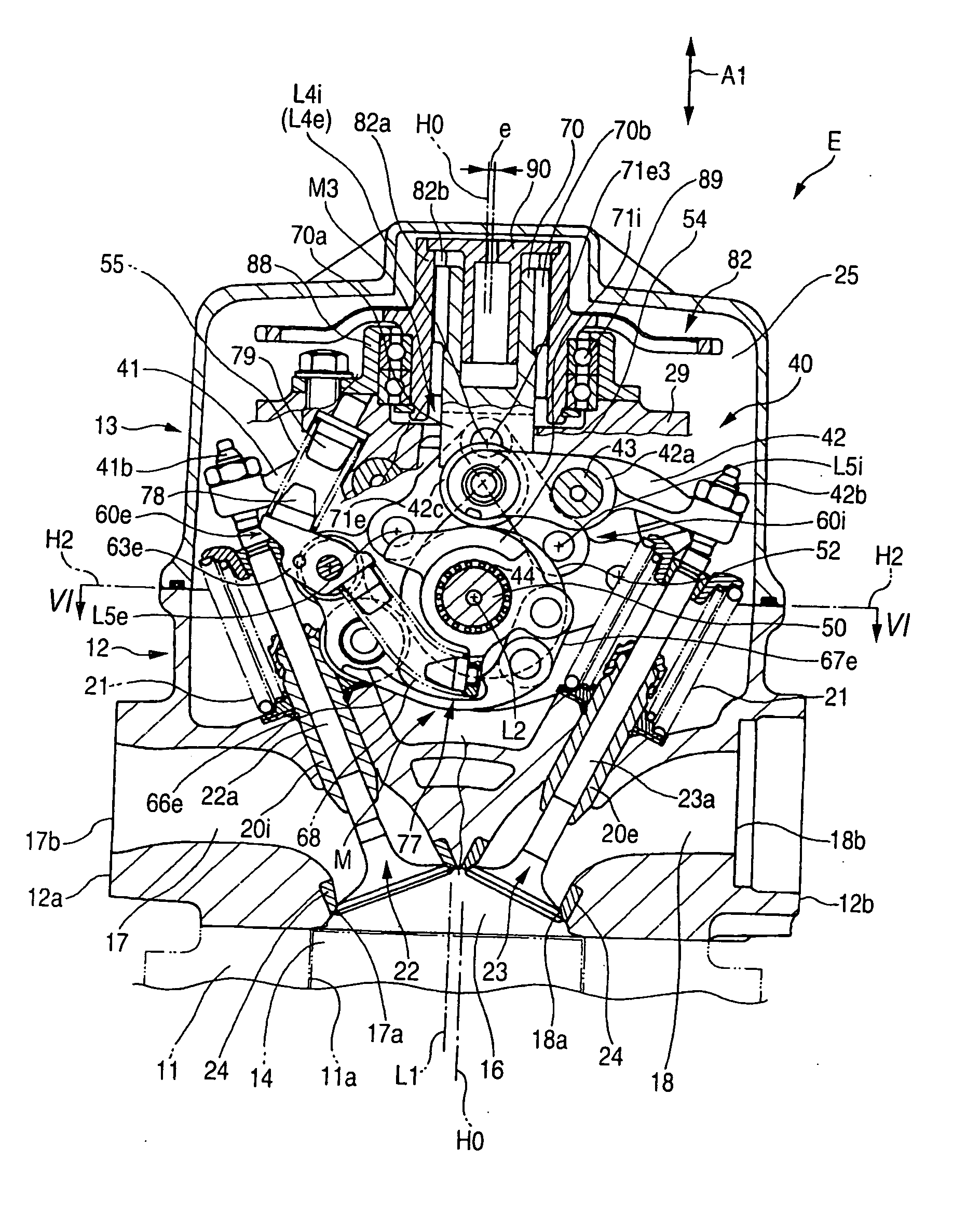
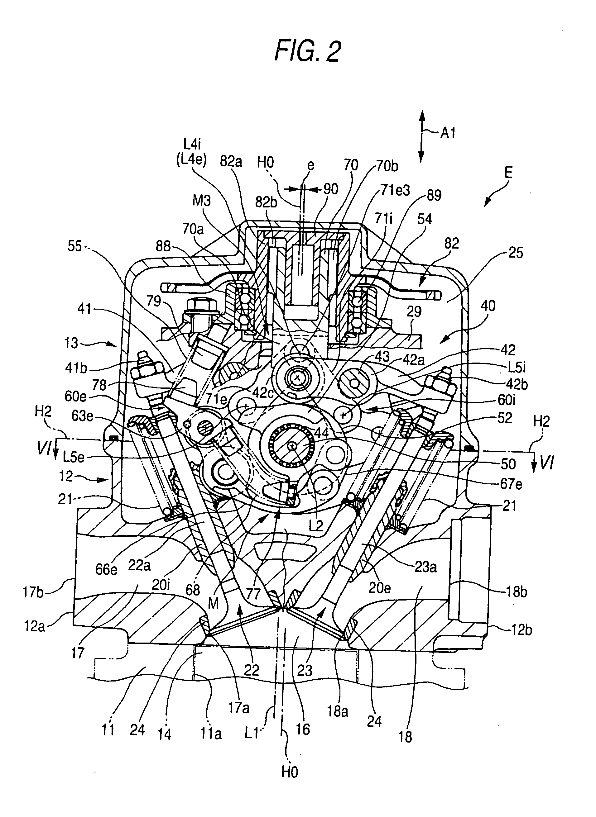
[0049]The power unit U comprises an internal combustion engine E which has a crankshaft 15 extending to the right and left of the mo...


PUM


Abstract

An internal combustion engine includes a throttle controlling mechanism; a valve characteristic varying mechanism which controls an internal EGR rate by the control of an overlap period Pa and a non-overlap period Pb; and an output setting means which sets a required amount of engine output. The throttle controlling mechanism controls an opening degree of a throttle valve to fully open the throttle valve at a predetermined load Da with an increase in an operating amount D in a first load range Fa which covers load range below the predetermined load Da in a low-load range, and to keeps the throttle valve fully opened in a second load range Fb which covers a load range over the predetermined load Da. The valve characteristic varying mechanism controls the engine output by controlling the overlap period Pa or the non-overlap period Pb according to the required amount D over the entire load range, and controls valve operation characteristics to obtain a maximum internal EGR rate at the predetermined load Da.

Description

TECHNICAL FIELD[0001]The present invention relates to a control method and a control apparatus of an internal combustion engine comprising a throttle controlling mechanism which opens or closes a throttle valve which controls an amount of intake air; and a valve operation device having a valve characteristic varying mechanism which controls valve operation characteristics including opening / closing timing of intake and exhaust valves.BACKGROUND ART[0002]In the field of internal combustion engine, various technologies for improving the fuel efficiency by decreasing the pumping loss are known. For example, an internal combustion engine disclosed in JP-A-2002-070597 comprises an intake operating angle changing mechanism for changing the operating angle of an intake valve; and a phase changing mechanism for changing the center phase of the operating angle of intake and exhaust valves. Also, in an middle-load range of the internal combustion engine, the decrease in the pumping loss, and t...

Claims


Application Information

Patent Timeline
Patent Type & Authority Applications(United States)
IPC IPC(8): F02B47/08F01L1/34F01L13/00F02M25/07F02B61/02F02D9/02F02D11/10F02D13/02F02D21/08F02D41/04F02D41/06F02D43/00
CPCF01L1/022Y02T10/18F01L13/0063F01L2001/0535F01L2013/0073F01L2105/00F01L2820/032F02B61/02F02D9/02F02D11/105F02D13/0211F02D13/0265F02D41/006F02D2041/002F02M25/0752F01L1/181F02M26/01F01L2305/00Y02T10/12A23L11/07A23C20/025A23V2002/00A23V2200/218
Inventor TANABE, KAZUYATSUTSUMIZAKI, TAKASHIINOMOTO, YUTAKATSUNASHIMA, KOSUKE
Owner HONDA MOTOR CO LTD
Why Eureka
Try Eureka