
Delta Flow Pressure Regulation

a technology of delta flow and pressure regulation, which is applied in the field of measuring and controlling the flow of delta gas into, can solve problems such as patient discomfort, and achieve the effects of reducing the dependency on the length and width of the breathing tube, constant pressure level, and hygieni

Inactive Publication Date: 2008-11-13
GENERAL ELECTRIC CO +1
View PDF12 Cites 56 Cited by
  • Summary
  • Abstract
  • Description
  • Claims
  • Application Information

AI Technical Summary

Benefits of technology

[0011]Since gas flow in breathing tubes and breathing masks at low pressures (<30 cmH2O) may be considered as homogenous, there is little time difference between patient breathing and actual flow sensor response. By applying a derivative signal analysis on the measured breathing gas flow, the delta energy term can be retrieved from the gas flow. This delta energy is proportional to pressure withdrawn or added into the breathing circuit and can therefore be used as an input into the pressure regulating function. By incorporating this delta energy flow value into the analyzing function for regulating the pressure, the use of a separate measuring tube is not needed. This system will also reduce the dependency of breathing tube length and width since the flow sensor may be located at the ventilator side of a breathing tube.
[0012]Other advantages of the present invention may be that it is possible to keep a constant pressure level and it constitutes a much more hygienic solution.
[0020]In another aspect of the present invention, a method for facilitating breathing in connection with a mechanical ventilator arrangement is provided, comprising the steps of:measuring a breathing gas flow and pressure;processing the breathing gas flow for flow changes;using the flow change values as pressure values; andresponding to changes of the pressure signal obtained from the flow change values in a breathing gas tubing by changing control signals for the mechanical ventilator, changing the pressure in the tubing to a set demand pressure using the measured pressure and flow changes as input parameters in a regulating procedure.
[0027]The processing unit may further be arranged to apply the flow curve to a filtering procedure in order to reduce noise.
[0029]The computer program may further be arranged to filter the flow signals prior to analyzing the flow data for flow changes in order to reduce noise.

Problems solved by technology

The time lag between patient effort and the breathing apparatus response in such a system will create a pressure drop in inhalation and a pressure peak in exhalation which creates pressure not being regulated within requirements, creating a discomfort for the patient.

Method used


Image

  • Delta Flow Pressure Regulation
  • Delta Flow Pressure Regulation
  • Delta Flow Pressure Regulation

Examples


Embodiment Construction

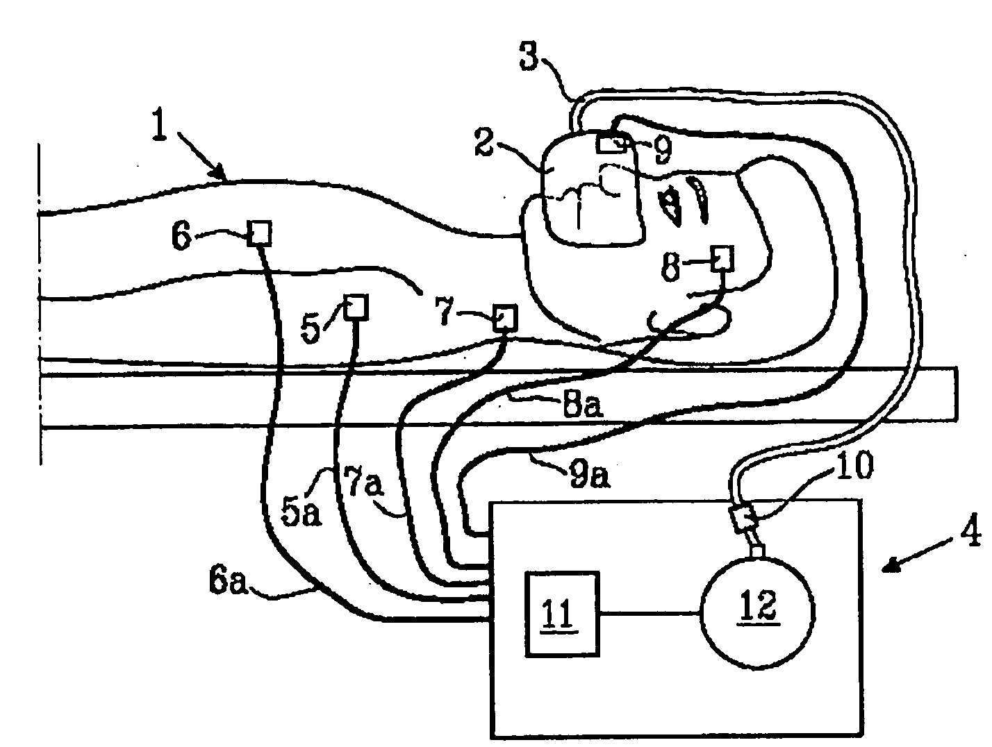
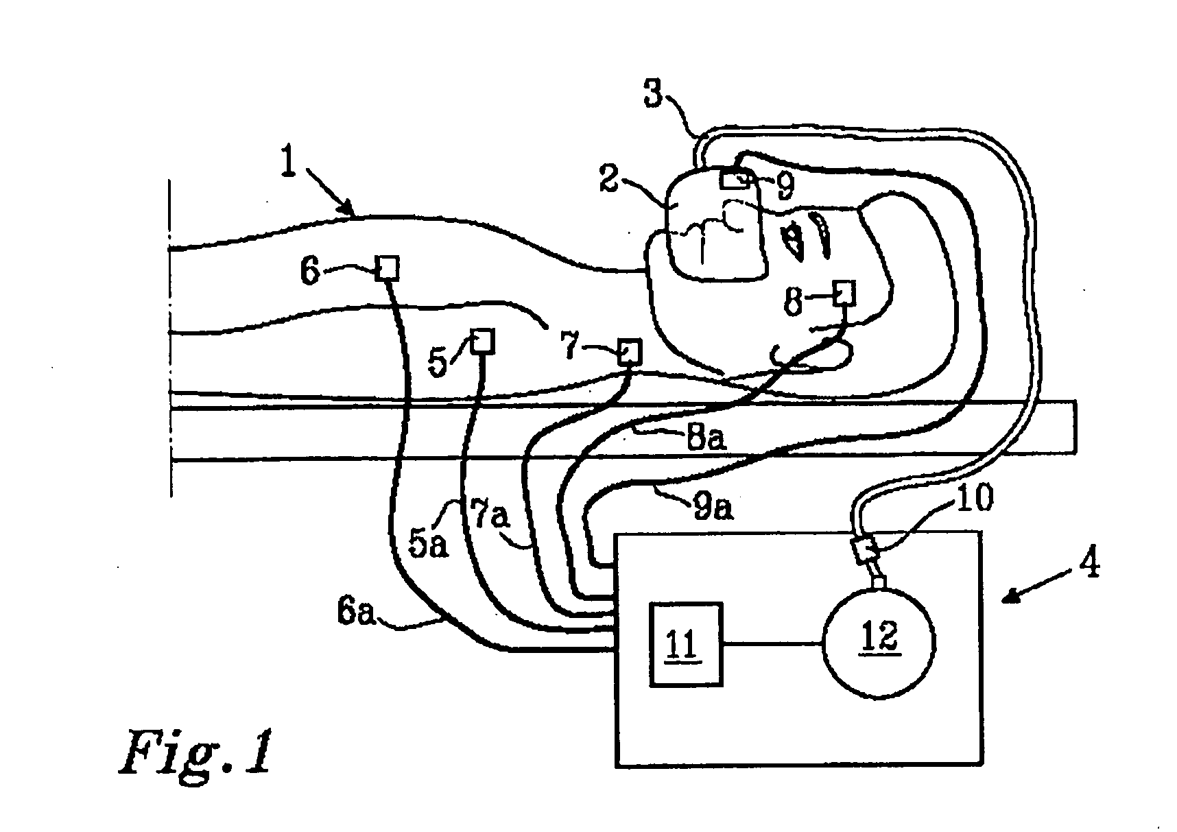
[0038]In FIG. 1 a schematic mechanical ventilation system used for the treatment of hypoventilation disorders is depicted. A ventilation system comprise a mechanical ventilator 4 supplying pressurized breathing gas, tubing 3 for guiding breathing gas to the patient 1, a breathing mask 2 or similar for administrating (supplying) the breathing gas to the patient 1, sensing means 5, 6, 7, 8, 9, and 10 for determining the physiological status of the patient 1. A mechanical ventilator 4 is supplying breathing gas for instance as a positive airway pressure via a tubing 3 and through a mask 2 to a patient 1. The mask 2 can be a face mask 2 covering both the mouth and nose or a nasal mask covering only the nose or nostrils depending on the patients needs. It can also be a hood covering the complete head or body of the patient.

[0039]The breathing gas may be of any suitable gas composition for breathing purposes as understood by the person skilled in the art, the composition depending on the ...


PUM


Abstract

A method, system, apparatus, and computer program for detecting breathing pattern changes and controlling a mechanical ventilator in accordance to changes of breathing air flow thus reducing the work of breathing for the patient.

Description

FIELD OF THE INVENTION[0001]The present invention relates to the measurement and control of breathing gas administration into humans, and more specifically the invention relates to a system for rapid response to changes of pressure / flow of breathing gas using delta flow control.BACKGROUND OF THE INVENTION[0002]Patients suffering from different forms of breathing disorders can be subject to several types of treatments depending on the illness or disorder present. Such treatments include surgical procedures, pharmacologic therapy, and non-invasive mechanical techniques. Surgical techniques to remedy breathing disorders constitute a considerable risk for the patient and can lead to permanent injury or even mortality. Pharmacologic therapy has in general proved disappointing with respect to treating certain breathing disorders, e.g. sleep apnea. It is therefore of interest to find other treatments, preferably non-invasive techniques.[0003]A mechanical ventilator represents a non-invasiv...

Claims


Application Information

Patent Timeline
IPC IPC(8): A61M16/00G05D7/06A61B7/00
CPCA61M16/0051A61M2016/0027A61M2016/0036A61M2205/3375A61M2205/3561A61M2205/50A61M2230/04A61M2230/10A61M2230/18A61M2230/205A61M2230/30A61M2230/432A61M2230/435A61M2230/50A61M2230/60A61M16/0069A61M16/024
Inventor TIEDJE, MIKAEL
Owner GENERAL ELECTRIC CO
Learn More