Shape of cone and air input annulus

a cone and air input technology, applied in catalyst activation/preparation, energy-based chemical/physical/physico-chemical processes, prosthesis, etc., can solve the problems of contaminating the output and reducing process control, and achieve the effect of reducing the occurrence of residues, rapid radiative heat loss, and high molecular weigh

Inactive Publication Date: 2008-11-13
SDC MATERIALS +1
View PDF101 Cites 62 Cited by
  • Summary
  • Abstract
  • Description
  • Claims
  • Application Information

AI Technical Summary

Benefits of technology

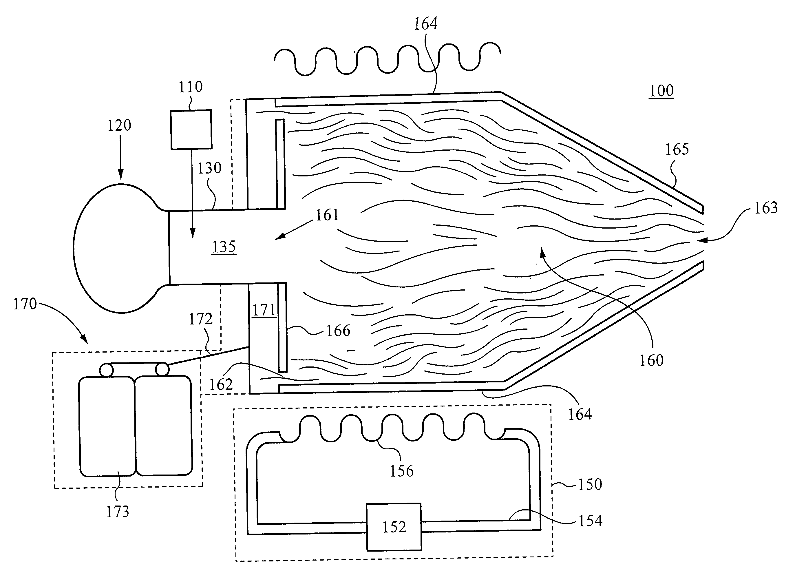
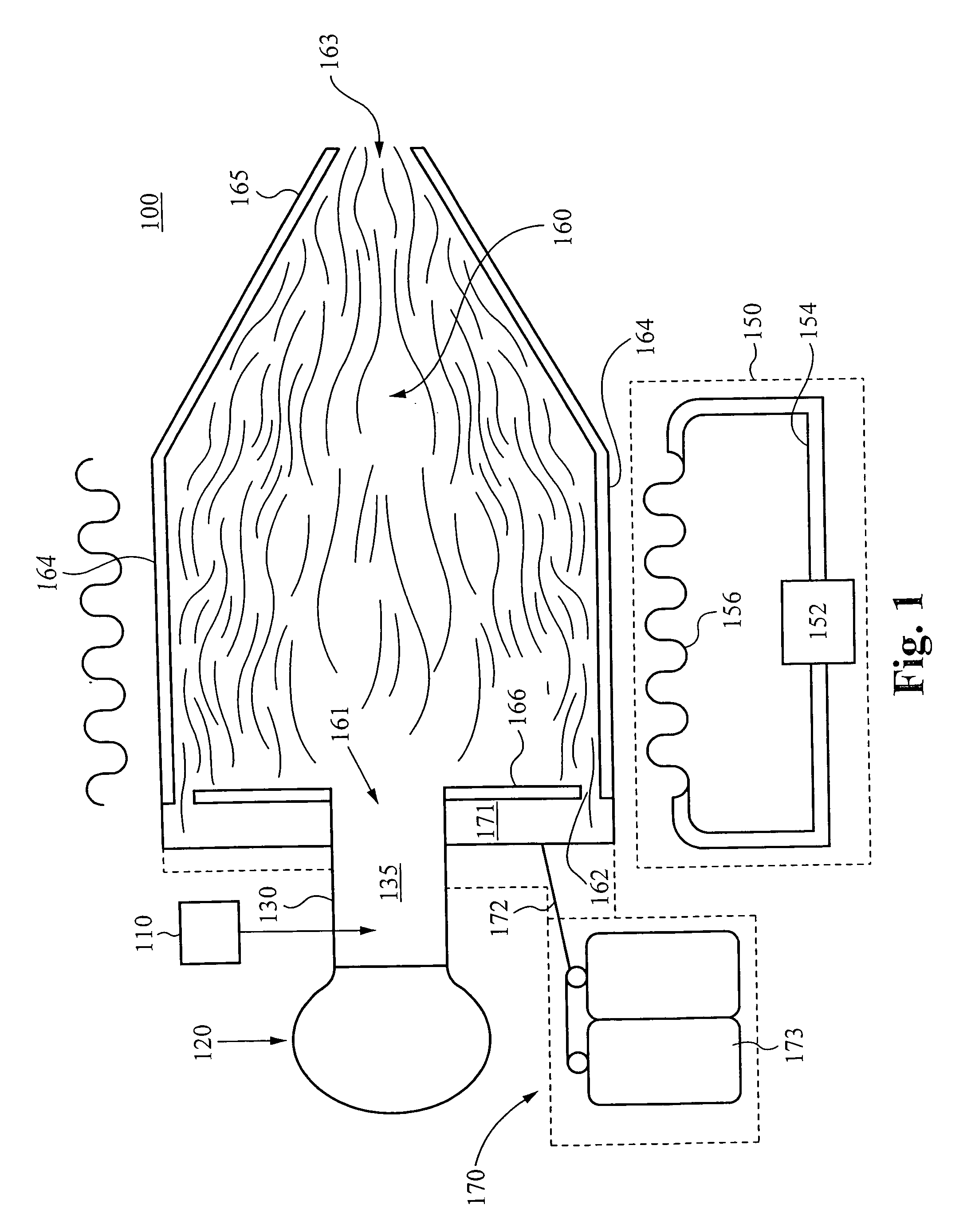
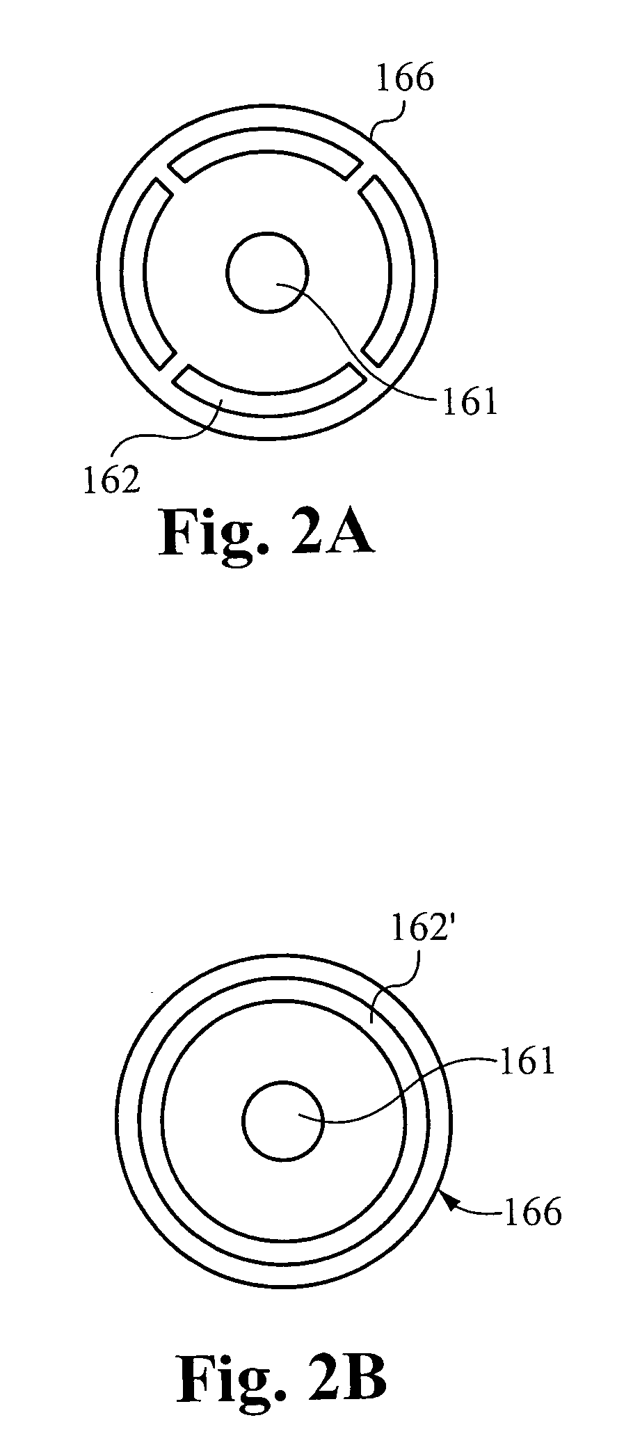
[0012]However, the occurrence of residue is minimized by the present invention, in which conditioning fluid flows through the one or more supply ports and along the inner surface of the constricting chamber, thereby providing a sheath of conditioning fluid between the gas-vapor mixture and the surface of the constricting chamber. In a preferred embodiment, the conditioning fluid is provided at a substantially cooler temperature than that of the gas-vapor mixture. Furthermore, the flow rate of the conditioning fluid is preferably substantially higher than that of the gas-vapor mixture. This disparity in flow rates allows for expansion of the gas-vapor mixture against the sheath of conditioning fluid and, to a certain degree, intermixture of the two fluids. However, the density and higher flow rate of the conditioning fluid substantially prevents the gas-vapor mixture from encountering the inner surfaces of the chamber. The composition of the conditioning fluid is determined partially with deference to the specific product being synthesized. Typically, the conditioning fluid is an inert gas, such as argon, neon or helium. Argon is preferred due to its higher molecular weight. Preferably, the conditioning fluid is supplied passively, as described more fully below, through a neutral pressure controlled atmosphere environment formed around the plurality of ports within the cover.
[0013]Furthermore, as described above, condensation of particles within the gas-vapor occurs rapidly upon flowing into the chamber and continues as the mixture flows through the chamber. These particles experience rapid radiative heat loss, as was also mentioned above. A certain amount of this radiation is absorbed by the conditioning fluid. However, as will be more fully explained below, a much larger fraction of the radiation is absorbed and dissipated by the chamber surfaces. More importantl...

Problems solved by technology

Expansion of the mixture gas against the inner surfaces of the constricting chamber can lead to adhesion thereto by particles within the gas and subsequently to the depositing of...

Method used


Image

  • Shape of cone and air input annulus
  • Shape of cone and air input annulus
  • Shape of cone and air input annulus

Examples


Embodiment Construction

[0026]The description below concerns several embodiments of the invention. The discussion references the illustrated preferred embodiment. However, the scope of the present invention is not limited to either the illustrated embodiment, nor is it limited to those discussed. To the contrary, the scope should be interpreted as broadly as possible based on the language of the Claims section of this document.

[0027]In the following description, numerous details and alternatives are set forth for purpose of explanation. However, one of ordinary skill in the art will realize that the invention can be practiced without the use of these specific details. In other instances, well-known structures and devices are shown in block diagram form in order not to obscure the description of the invention with unnecessary detail.

[0028]This disclosure refers to both particles and powders. These two terms are equivalent, except for the caveat that a singular “powder” refers to a collection of particles. T...


PUM

PropertyMeasurementUnit
Temperatureaaaaaaaaaa
Flow rateaaaaaaaaaa
Energyaaaaaaaaaa

Abstract

A constricting chamber having first and second ends, the chamber comprising: an interior surface formed between the first and second ends, disposed circumferentially around and defining an interior space and a longitudinal axis of the chamber; a frusto-conical surface disposed between the first and second ends and narrowing as it extends away from the first end and into the second end; an ejection port disposed at the second end and substantially aligned with the longitudinal axis; a cover disposed at the first end, substantially perpendicular to the longitudinal axis, and comprising a center substantially aligned with the longitudinal axis; an injection port disposed on the cover proximate the center, and configured to receive a reactive mixture into the chamber; and an annular supply portion disposed circumferentially around the longitudinal axis and comprising supply port(s) configured to supply conditioning fluid into the chamber in an annular formation along the interior surface.

Description

CROSS-REFERENCE TO RELATED APPLICATIONS[0001]The present application claims priority to co-pending U.S. patent application Ser. No. 11 / 110,341, filed on Apr. 19, 2005, entitled, “HIGH THROUGHPUT DISCOVERY OF MATERIALS THROUGH VAPOR PHASE SYNTHESIS” and to co-pending U.S. Provisional Application Ser. No. 60 / 928,946, filed May 11, 2007, entitled “MATERIAL PRODUCTION SYSTEM AND METHOD,” both of which are hereby incorporated by reference as if set forth herein.FIELD OF THE INVENTION[0002]Gas or vapor phase particle production is an important technique for producing engineered materials, especially nano-materials. The present invention relates to methods of cooling, collecting and controlling the flow of a reactive medium containing gas or vapor phase particles.BACKGROUND OF THE INVENTION[0003]Specific characteristics of particles produced in gas or vapor phase synthesis reactions depend not only on the energy delivered to the reactive medium, but also on the conditioning of the reactive...

Claims


Application Information

Patent Timeline
IPC IPC(8): B01J19/08B01J19/00
CPCB22F9/12Y10T156/15F28D7/024F28D7/08F28D15/00F28F27/00B22F2999/00B01J19/0013Y10S623/923B01J25/00B01J25/02Y10S623/92B22F2202/13Y10T137/0391Y10T137/2076A61L2/18B22F2203/13B01J19/088B01J37/0018B01J37/349B01J37/06B01J2219/0805B01J2219/0894B01J2/16B01J35/04B01J37/0027B01J2219/0879F28C3/16
Inventor LAYMAN, FREDERICK P.BIBERGER, MAXIMILIAN A.
Owner SDC MATERIALS
Why Eureka
Try Eureka