
Source driver and gamma correction method thereof

a source driver and gamma correction technology, applied in the field of source drivers, can solve the problems of difficult reduction of fabrication cost, large layout area of the conventional source driver, and large layout area of the source driver, so as to improve gamma correction performance, reduce fabrication cost, and reduce circuit layout area

Inactive Publication Date: 2008-11-13
DENMOS TECH
View PDF7 Cites 7 Cited by
  • Summary
  • Abstract
  • Description
  • Claims
  • Application Information

AI Technical Summary

Benefits of technology

[0013]The present invention is directed to a source driver and a Gamma correction method thereof, so as to reduce the circuit layout area, reduce the fabrication cost, and improve the Gamma correction performance.
[0017]In the source driver and the Gamma correction method thereof according to an embodiment of the present invention, the bit of the corrected image data is larger than the bit of the original image data, so as to obtain a preferred resolution to enhance the Gamma correction performance.
[0018]In view of the above, the present invention provides a Gamma correction method to obtain a corrected image data. As the source driver of the present invention employs a Gamma correction unit to carry out the Gamma correction performance, the source driver can adopt a linear DAC. Accordingly, the present invention can reduce the chip area of the source driver, and shorten the resistance matching time of the layout process during the fabrication, thus reducing the fabrication cost of the source driver. According to an embodiment of the present invention, the bit of the corresponding corrected image data is larger than the bit of the original image data, so as to increase the resolution, and thus obtain a preferred Gamma correction performance.

Problems solved by technology

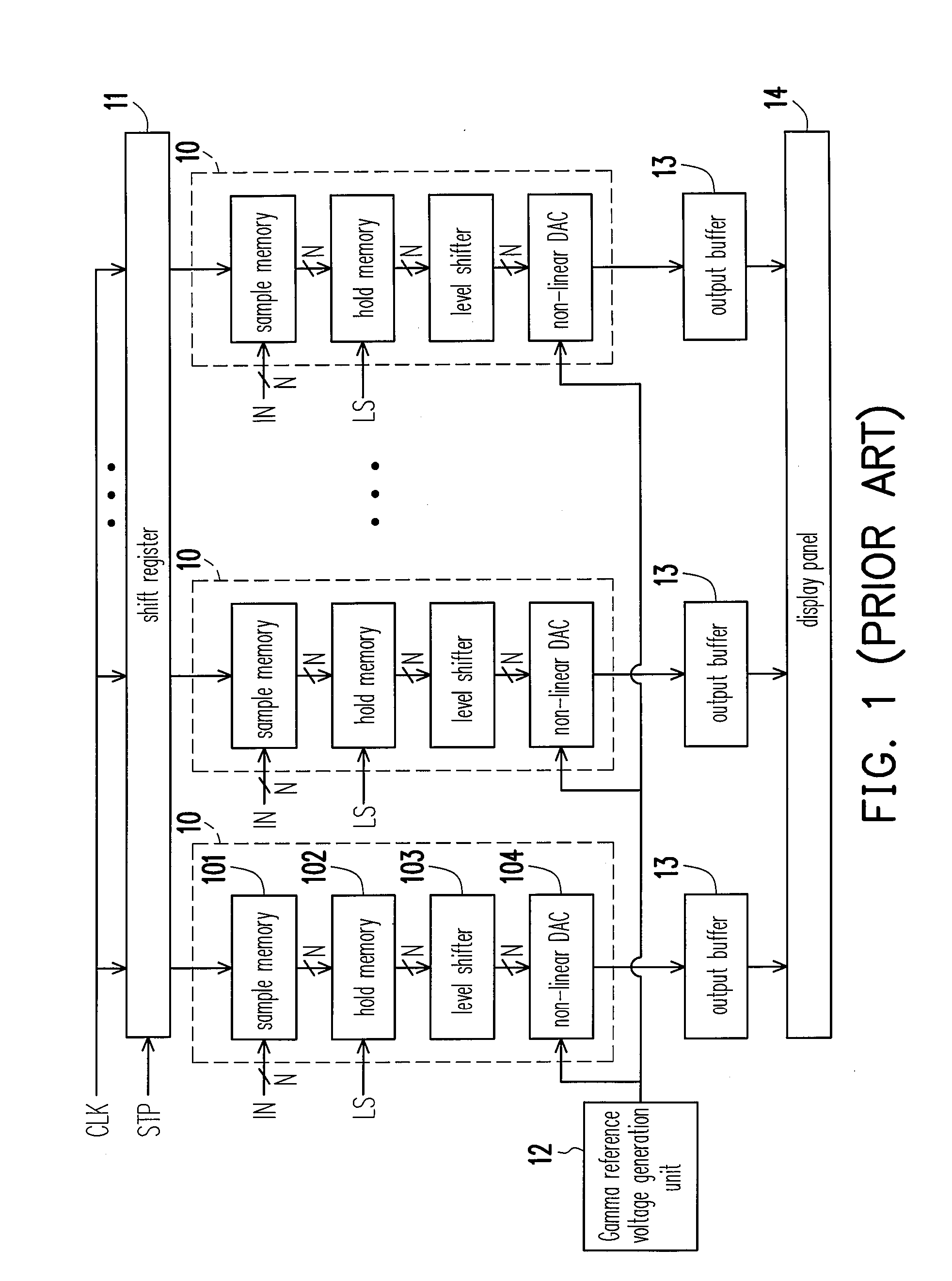
However, this conversion scheme demands larger quantity of resistors, switchers, and operational amplifiers, such that the layout area of the source driver becomes very large.
Thus, the layout area of the conventional source driver is very large.
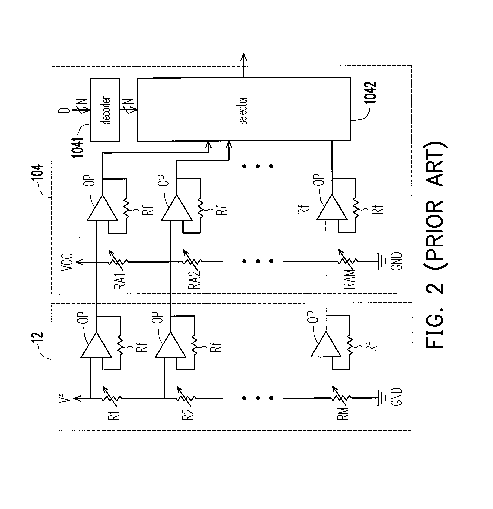
. . RM must be trimmed precisely, thus making it difficult to reduce the fabrication cost.
Thus, a larger quantity of resistors, operational amplifiers, and converters will enlarge the layout area of the chip, and thus increase the manufacturing cost, which does not meet the present trend of being light, thin, short, and small.
Furthermore, the precision of the DAC depends on the matching degree of the resistors (i.e., the resistance ratio of the bleeder resistors), and if plenty of resistors need precise matching, the time of the layout process will be largely consumed.

Method used


Image

  • Source driver and gamma correction method thereof
  • Source driver and gamma correction method thereof
  • Source driver and gamma correction method thereof

Examples


Embodiment Construction

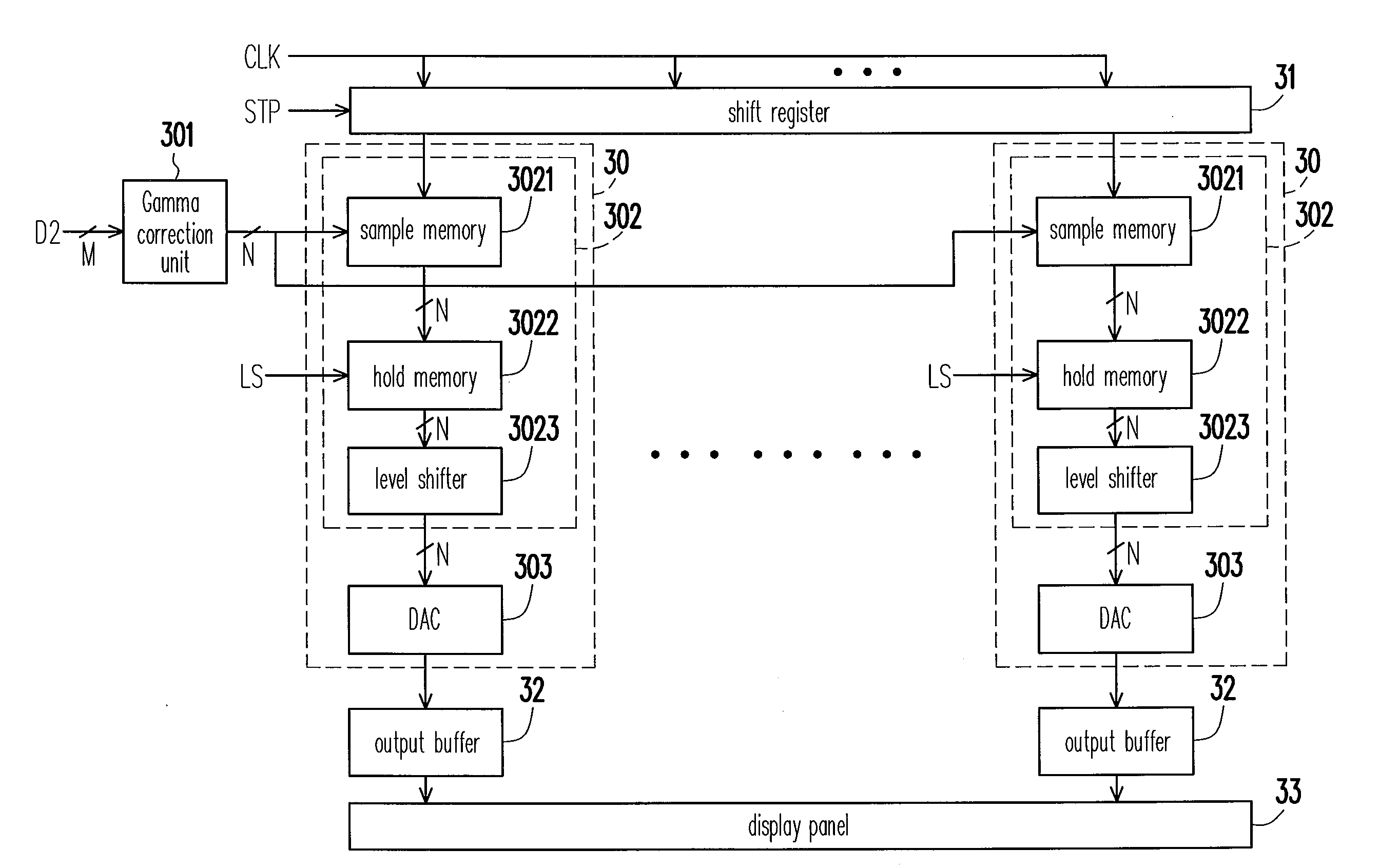
[0032]Referring to FIG. 3, a circuit block diagram of a source driver according to an embodiment of the present invention. The source driver includes a plurality of source drive units 30 and a shift register 31. A trigger end of the shift register 31 receives a clock signal CLK, and an input end of the shift register 31 receives a start pulse STP. Each source drive unit 30 is coupled to an output end of a corresponding shift register 31. Each source drive unit 30 includes a Gamma correction unit 301, a latch unit 302, and a digital-to-analog converter (DAC) 303. The input end of the Gamma correction unit 301 is used for receiving an original image data IN. The latch unit includes a sample memory 3021, a hold memory 3022, and a level shifter 3023. An input end of the sample memory 3021 is coupled to an output end of the Gamma correction unit 301, and an output end of the sample memory 3021 is coupled to an input end of the hold memory 3022. A trigger end of the hold memory 3022 is co...


PUM


Abstract

A source driver and a Gamma correction method thereof with lower layout area and preferred Gamma correction performance are provided. The source driver includes a Gamma correction unit, a latch unit, and a digital-to-analog converter (DAC). The Gamma correction unit receives an original image data, and converts the original image data to a corresponding corrected image data. The latch unit is coupled to the Gamma correction unit. The DAC is coupled to the latch unit, so as to convert the corrected image data to a corresponding analog drive signal. In the Gamma correction method, first, a correction unit to correct an original image data to a corresponding corrected image data is provided, and the corrected image data is converted into a corresponding analog drive signal.

Description

CROSS-REFERENCE TO RELATED APPLICATION[0001]This application claims the priority benefit of Taiwan application serial no. 96116456, filed May 9, 2007. All disclosure of the Taiwan application is incorporated herein by reference.BACKGROUND OF THE INVENTION[0002]1. Field of the Invention[0003]The present invention relates to a source driver. More particularly, the present invention relates to a source driver and a Gamma correction method thereof with lower layout area and preferred Gamma correction performance for driving a display panel.[0004]2. Description of Related Art[0005]Currently, display panel has been widely utilized in various products, such as TV sets, and computer screens. The display panel requires a source driver to drive the display panel and control the brightness of the image through the Gamma correction performance of the source driver, so as to achieve a preferred image quality.[0006]FIG. 1 is a circuit diagram of a conventional source driver. The conventional sour...

Claims


Application Information

Patent Timeline
IPC IPC(8): G09G3/30G06K9/40G09G3/36G09G5/02
CPCG09G3/2011G09G2310/027G09G2320/0276G09G2330/028G09G2340/0428
Inventor CHANG, SHING-WEI
Owner DENMOS TECH
Learn More