Wavelength Division Multiplexed Passive Optical Network

a passive optical network and wavelength division technology, applied in the field of fiber optic transmission systems, can solve the problems of difficult and expensive supply of reliable power to outside plants, uncontrolled environment, equipment installation,

Active Publication Date: 2008-11-13
NEC CORP
View PDF3 Cites 35 Cited by
  • Summary
  • Abstract
  • Description
  • Claims
  • Application Information

AI Technical Summary

Problems solved by technology

FTTP, however, often requires installation of equipment in outside plant, which is typically exposed to uncontrolled environments.
Supplying reliable power to outside plant is also more difficult and expensive than supplying reliable power to a central office, for example.
Furthermore, since communications links are geographically dispersed over many customers, management of the distribution plant is more difficult than management of the infrastructure of a central office, for example.

Method used


Image

  • Wavelength Division Multiplexed Passive Optical Network
  • Wavelength Division Multiplexed Passive Optical Network
  • Wavelength Division Multiplexed Passive Optical Network

Examples


Embodiment Construction

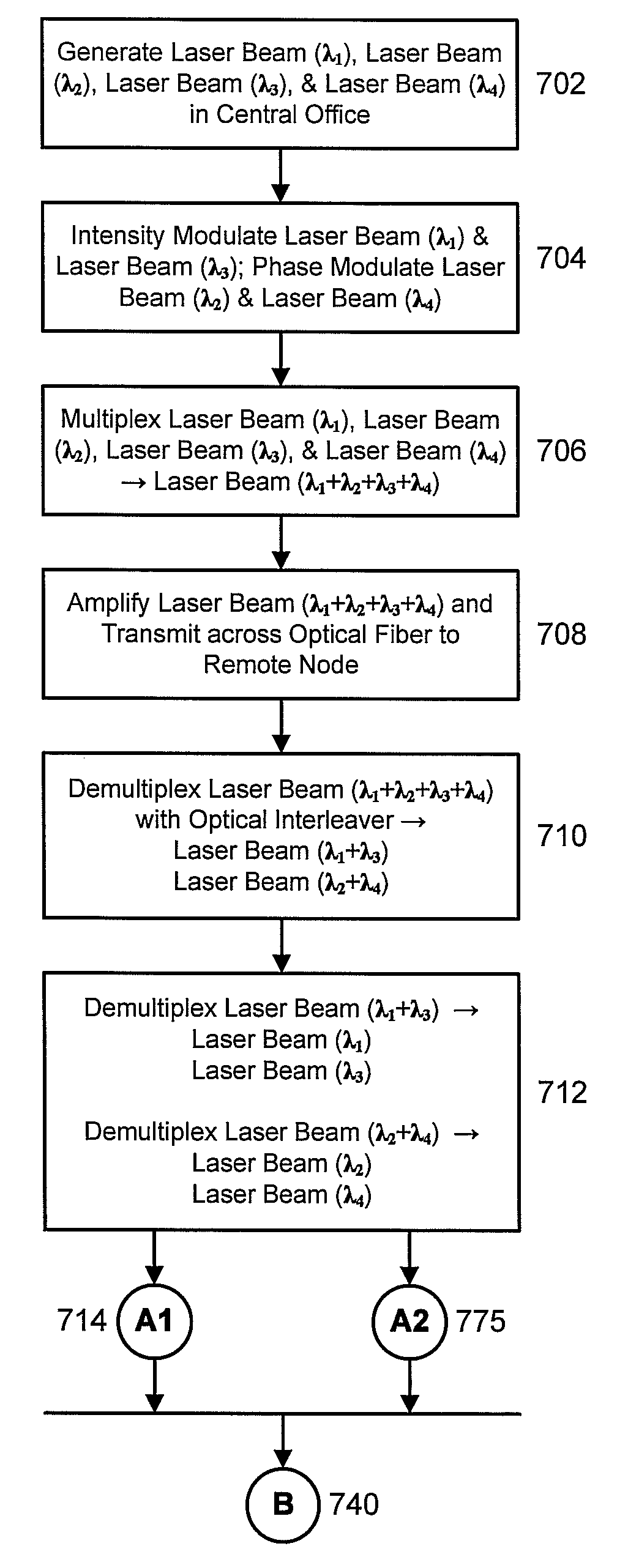
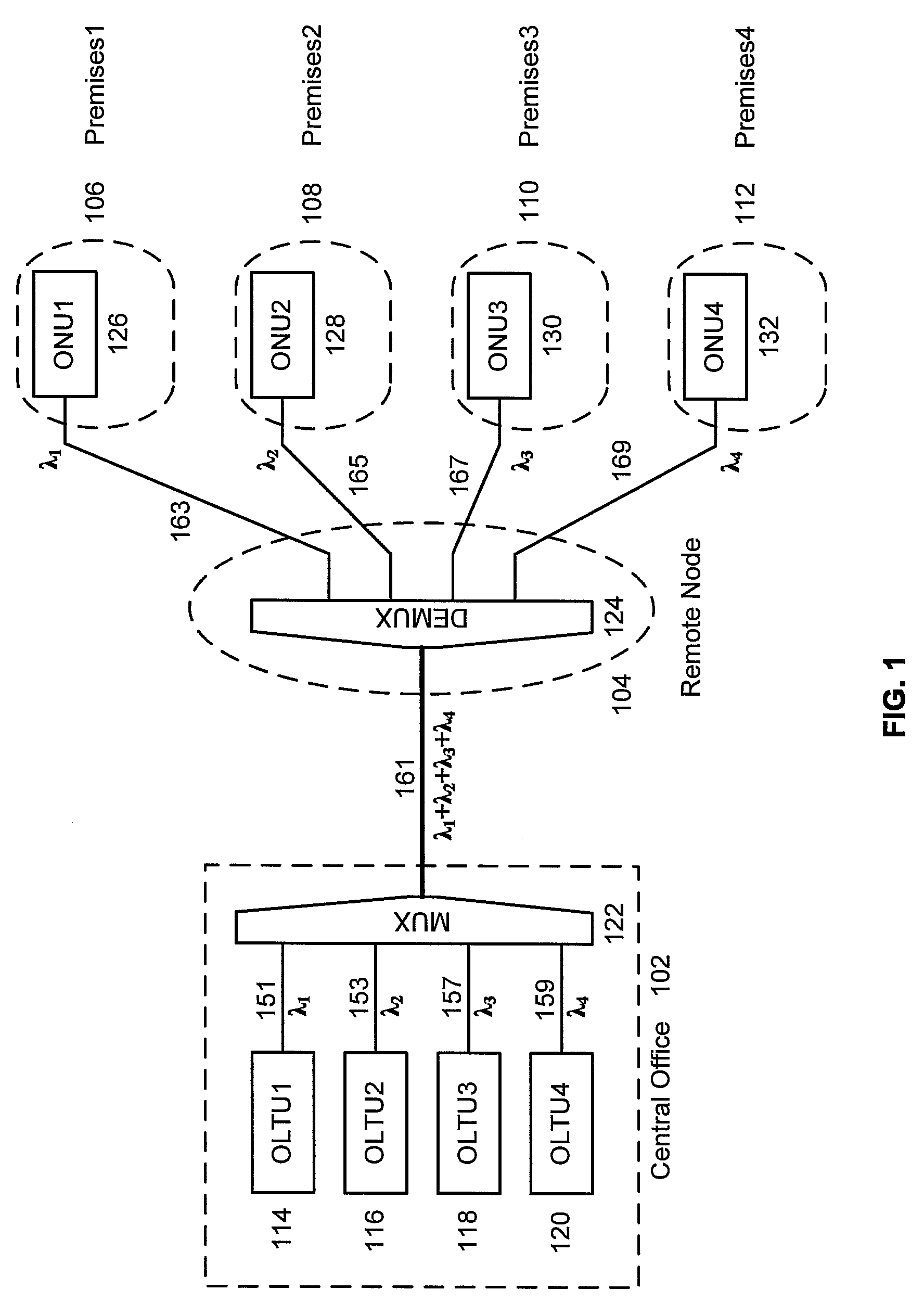
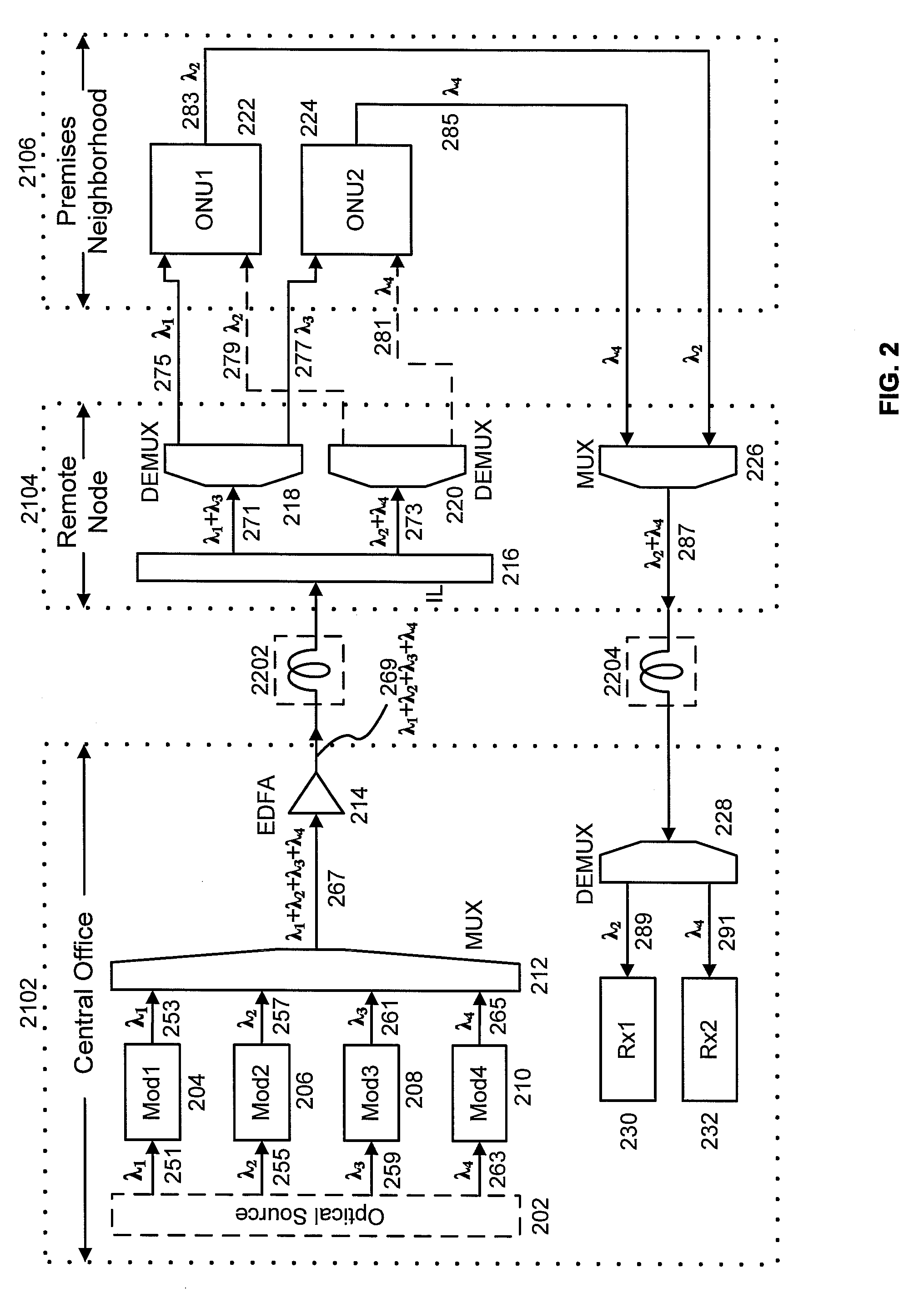
[0015]Shown in FIG. 1 is a high-level schematic of an example of a FTTP network based on wavelength division multiplexing. The primary locations involved are the central office 102, the remote node 104, and premises1106-premises4112. The example shows a single remote node and four premises. In general, multiple remote nodes may be serviced by a single central office, and multiple premises may serviced by a single remote node. Remote node 104 is also referred to as a neighborhood node, which services the neighborhood comprising premises1106 to premises4112. As discussed above, central office 102 typically has a well-regulated environment and reliable power sources. The remote node 104, however, is typically installed in outdoor plant.

[0016]For simplicity, FIG. 1 shows an example of a network providing uni-directional services, in which data is transported downstream from the central office 102 to premises1106—premises4112. Examples of networks providing bidirectional services are dis...


PUM


Abstract

Data is transmitted between a central office and customer premises by a wavelength division multiplex passive optical network. Two laser beams with separate wavelengths are transmitted from the central office to an optical network unit in the customer premises. Both laser beams carry downstream data. One laser beam is intensity modulated by on/off keying. The other laser beam is phase modulated by differential phase shift keying, which maintains a constant optical intensity. The first laser beam is received by a first optical receiver, which demodulates the first downstream data. The second laser beam is split in two. One laser beam is sent to a second optical receiver, which demodulates the second downstream data. The other laser beam is sent to a reflective semiconductor amplifier, which modulates the beam with upstream data and transmits the beam back to a receiver in the central optical system.

Description

[0001]This application claims the benefit of U.S. Provisional Application No. 60 / 916,335 filed May 7, 2007, which is incorporated herein by reference.BACKGROUND OF THE INVENTION[0002]The present invention relates generally to fiber optic transmission systems, and more particularly to wavelength division multiplexed passive optical networks.[0003]Fiber optics is a reliable technology for high-speed packet data transmission in telecommunications networks. It has been extensively deployed in core networks, in which the network equipment is typically installed in controlled environments. Environmental variables, such as temperature, humidity, vibration, and shock, are typically regulated according to industry standards. In addition, these installations typically have reliable power sources, including battery backup.[0004]Multimedia services (data, voice, and video) are increasingly being provided over packet data networks. These services require high-speed communication links between cu...

Claims


Application Information

Patent Timeline
Patent Type & Authority Applications(United States)
IPC IPC(8): H04J14/02H04B10/2581
CPCH04B10/2587H04J14/0282
Inventor YU, JIANJUNLUO, YUANQIUHU, JUNQIANGWANG, TING
Owner NEC CORP
Why Eureka
Try Eureka