RF transmitter with adjustable antenna assembly

a technology of antenna assembly and rf transmitter, which is applied in the direction of antennas, diversity/multi-antenna systems, electrically long antennas, etc., can solve the problems of antenna consumption a relatively large area of pcb, antenna occupies a significant amount of space, and its three-dimensional aspects cannot be implemented on a planer substra

Inactive Publication Date: 2008-11-13
AVAGO TECH WIRELESS IP SINGAPORE PTE
View PDF15 Cites 186 Cited by
  • Summary
  • Abstract
  • Description
  • Claims
  • Application Information

AI Technical Summary

Problems solved by technology

The in-air helix antenna provides a magnetic omni-directional mono pole antenna, but occupies a significant amount of space and its three dimensional aspects cannot be implemented on a planer substrate, such as a printed circuit board (PCB).
Such an antenna consumes a relatively large area of the PCB.
If the RF transceiver is a multiple band transceiver (e.g., 900 MHz and 2400 MHz), provides beamforming, provides polarization, provides diversity, and / or provides multiple in-band communications, then two antennas are needed, which consumes even more PCB space.
In addition, due to multiple path fading, the received signals have distortion (e.g., amplitude error and / or phase error) with respect to the transmitted signals.
There are many solutions to overcome this problem once the received RF signals are converted to baseband, however, there are few, if any, solutions to correct this problem in RF.

Method used


Image

  • RF transmitter with adjustable antenna assembly
  • RF transmitter with adjustable antenna assembly
  • RF transmitter with adjustable antenna assembly

Examples


Embodiment Construction

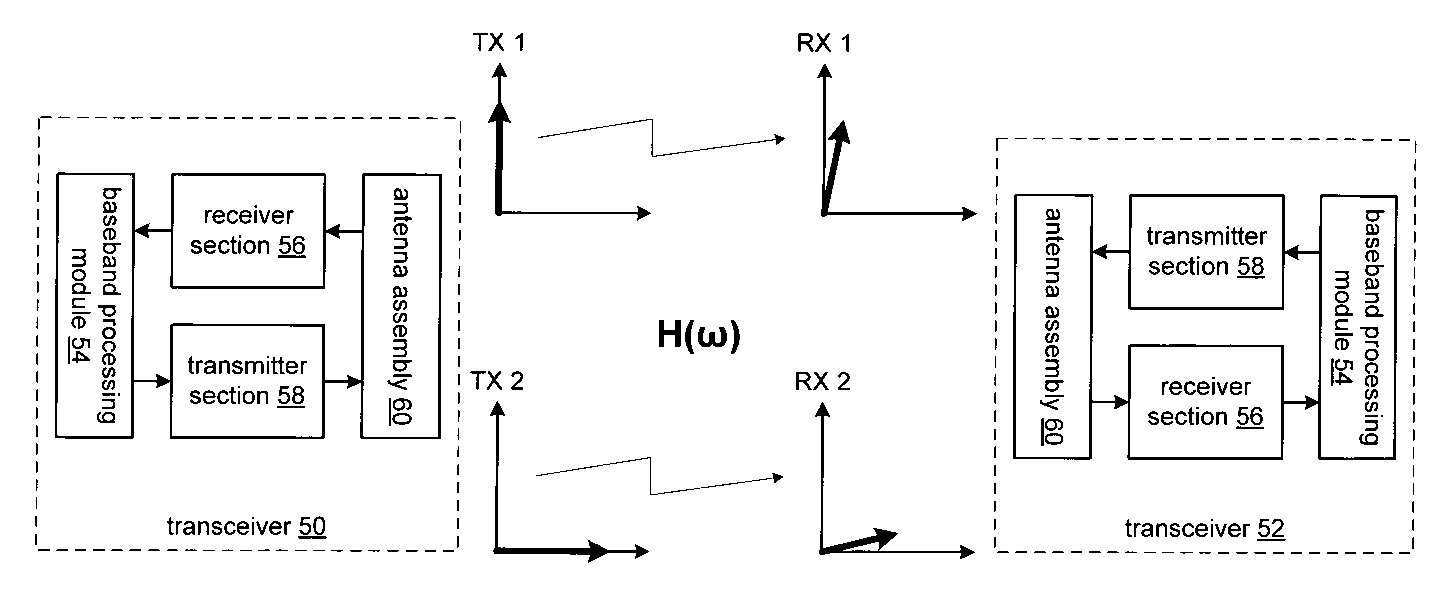
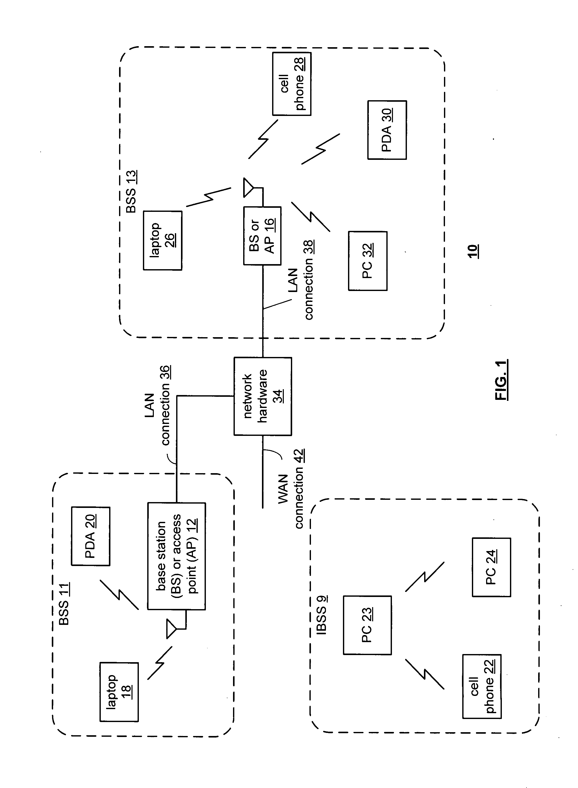
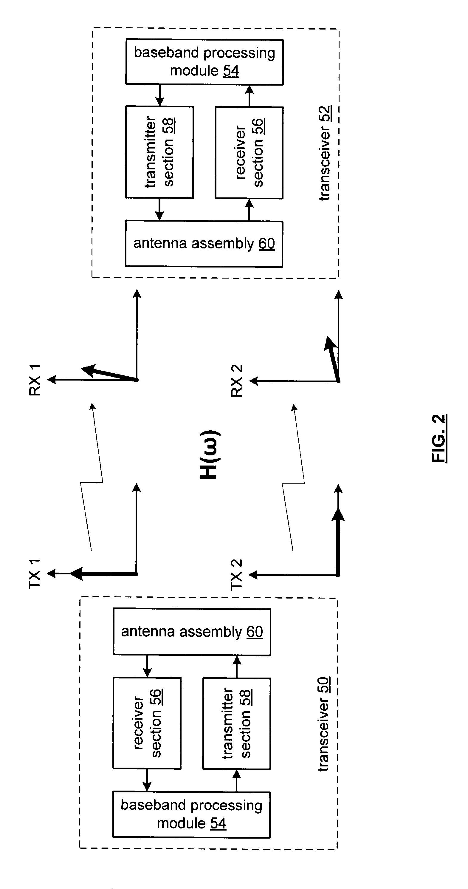
[0043]FIG. 1 is a schematic block diagram illustrating a communication system 10 that includes a plurality of base stations and / or access points 12, 16, a plurality of wireless communication devices 18-32 and a network hardware component 34. Note that the network hardware 34, which may be a router, switch, bridge, modem, system controller, et cetera provides a wide area network connection 42 for the communication system 10. Further note that the wireless communication devices 18-32 may be laptop host computers 18 and 26, personal digital assistant hosts 20 and 30, personal computer hosts 24 and 32 and / or cellular telephone hosts 22 and 28 that include a wireless RF transceiver.

[0044]Wireless communication devices 22, 23, and 24 are located within an independent basic service set (IBSS) area and communicate directly (i.e., point to point). In this configuration, these devices 22, 23, and 24 may only communicate with each other. To communicate with other wireless communication devices...


PUM


Abstract

A radio frequency (RF) transmitter includes a baseband processing module, an up conversion module, a power amplifier module, and an antenna assembly. The baseband processing module is coupled to convert outbound data into a first outbound symbol stream and a second outbound symbol stream and to generate an adjust signal. The up conversion module is coupled to convert the first outbound symbol stream into a first up converted signal and to convert the second outbound symbol stream into a second up converted signal. The power amplifier module is coupled to amplify the first and second up converted signals to produce first and second outbound RF signals. The antenna assembly is coupled to transmit the first and second outbound RF signals, wherein the antenna assembly adjusts at least one of amplitude and phase of at least one of the first and second outbound RF signals based on the adjust signal.

Description

CROSS REFERENCE TO RELATED PATENTS[0001]Not applicableSTATEMENT REGARDING FEDERALLY SPONSORED RESEARCH OR DEVELOPMENT[0002]Not applicableINCORPORATION-BY-REFERENCE OF MATERIAL SUBMITTED ON A COMPACT DISC[0003]Not applicableBACKGROUND OF THE INVENTION[0004]1. Technical Field of the Invention[0005]This invention relates generally to wireless communication systems and more particularly to antennas used within such wireless communication systems.[0006]2. Description of Related Art[0007]Communication systems are known to support wireless and wire lined communications between wireless and / or wire lined communication devices. Such communication systems range from national and / or international cellular telephone systems to the Internet to point-to-point in-home wireless networks to radio frequency identification (RFID) systems. Each type of communication system is constructed, and hence operates, in accordance with one or more communication standards. For instance, wireless communication sy...

Claims


Application Information

Patent Timeline
Patent Type & Authority Applications(United States)
IPC IPC(8): H04B1/02
CPCH01Q3/26H01Q9/285H04B7/10
Inventor ROFOUGARAN, MARYAM
Owner AVAGO TECH WIRELESS IP SINGAPORE PTE
Why Eureka
Try Eureka