
Auto Signal Output Device

a technology of audio signal and output device, which is applied in the direction of recording signal processing, instruments, code conversion, etc., can solve the problems of inability to reproduce the sound of compact discs in which high-range components are not reproduced, short smoothing degrees of the obtained signal waveform, and inability to achieve reproducibility with fidelity in the vicinity of high-range components. , to avoid the effect of signal discontinuation

Active Publication Date: 2008-11-20
D & M HOLDINGS INC
View PDF15 Cites 8 Cited by
  • Summary
  • Abstract
  • Description
  • Claims
  • Application Information

AI Technical Summary

Benefits of technology

The present invention relates to an audio signal output device that improves sound quality by filtering high-range components from compact discs and other audio signals. The device uses digital filters to oversample and interpolate the audio data, and then adds the high-range components back in a smooth manner to reproduce the original waveform with fidelity. The invention also includes a judging unit to determine the frequency of reversals in polarity of the audio signal, which helps select the appropriate output based on the characteristics of the audio signal. The invention aims to improve sound quality and provide a more faithful reproduction of the original analog audio signals.

Problems solved by technology

As a consequence, some users may not be satisfied with the sound of compact discs in which high-range components are not reproduced as compared with the sound reproduced by conventional analog systems.
Further, in cases in which high-range components are added by way of zero-order interpolation using a digital filter, smoothing degrees of the obtained signal waveforms may be slightly short.
However, since the sampling points in the vicinity of the high range (e.g., frequency equal to ½ of sampling frequency “fs”) are intricately changed, reproducibility with fidelity in the vicinity of the high range can rarely be achieved using the oversampling method with employment of spline interpolation or Lagrange interpolation.
In other words, it is difficult to obtain faithful reproductions of waveforms of original analog audio signals as waveforms of analog audio signals after being D / A-converted.
Thus, distortions may readily occur.
When Lagrange interpolation is employed, any influence from aliasing noise is readily given, causing distortions to readily occur.
As described above, in the case in which oversampling processing by way of spline interpolation or Lagrange interpolation which couples the sampling points to each other in a smooth manner is employed, problems arise in that the reproducibility with a fidelity near the high range (fs / 2) can rarely be obtained, and distortion may easily occur.

Method used


Image

  • Auto Signal Output Device
  • Auto Signal Output Device
  • Auto Signal Output Device

Examples


Embodiment Construction

[0043]Referring now to the figures, an example of embodiments of the present invention will be described.

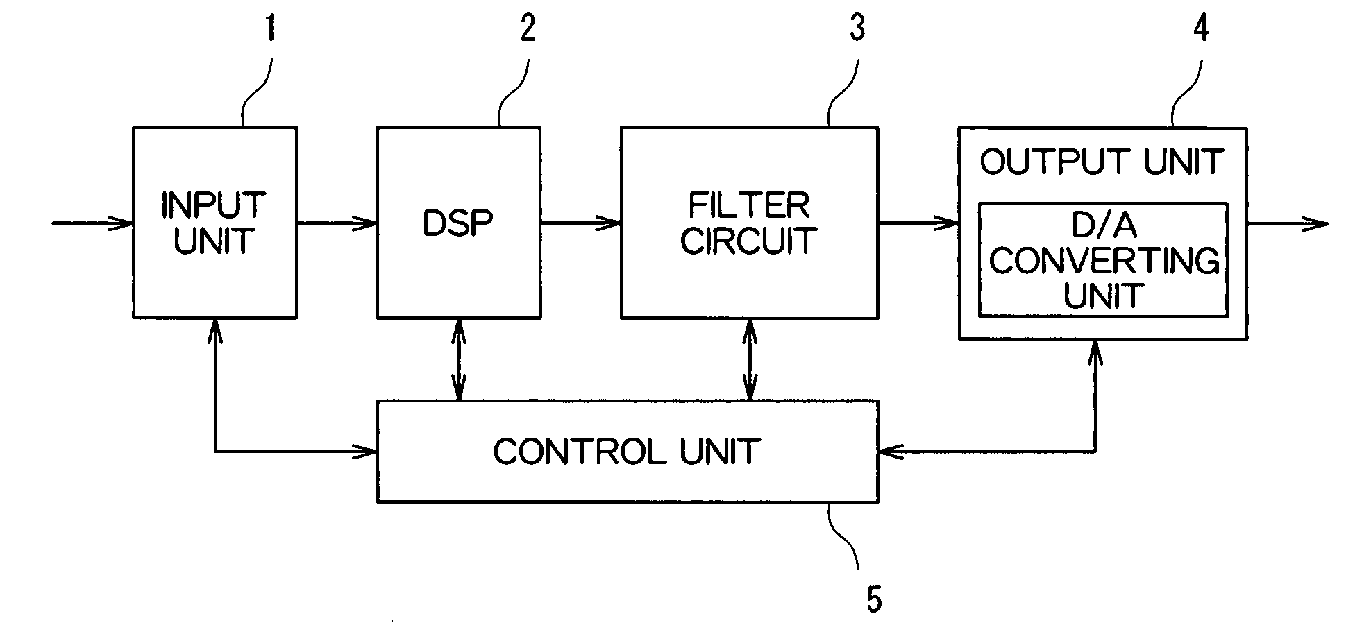
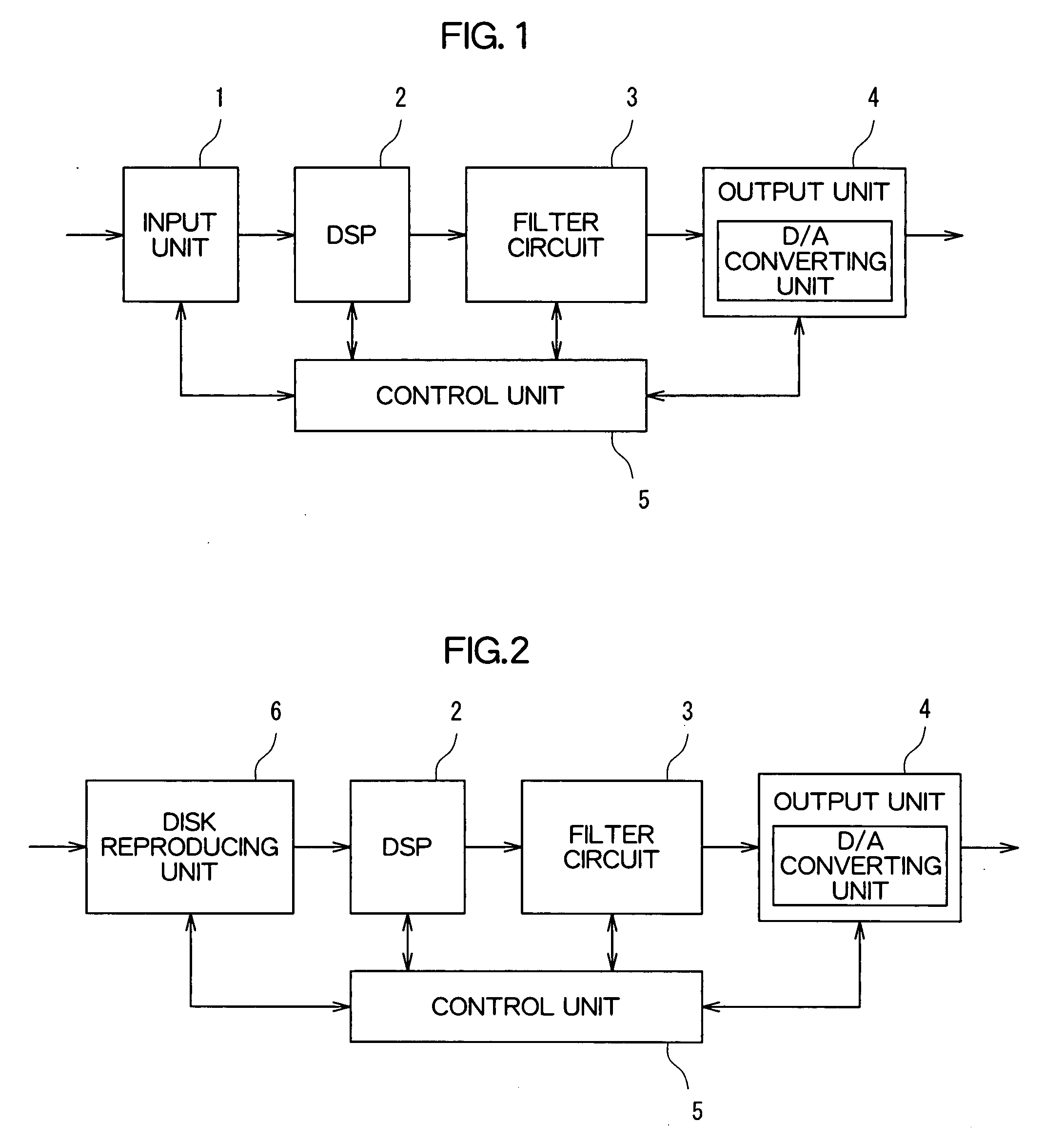
[0044]FIG. 1 is a block diagram of an audio signal output device according to an embodiment of the present invention. The audio signal output device shown in FIG. 1 includes an input unit 1, a DSP (Digital Signal Processor) 2, a filter circuit 3, an output unit 4, and a control unit 5. The audio signal output device is an amplifying apparatus such as an audio visual (AV) amplifier. Digital audio data output from a reproducing apparatus such as a CD (Compact Disk) player and a DVD (Digital Versatile Disc) player is input to the audio signal output device.

[0045]The input unit 1 accepts an input of the digital audio data (digital audio signal) from the reproducing apparatus.

[0046]The DSP 2 performs signal processing such as expansion and adding of reverberation sound with respect to the digital audio data input to the input unit 1.

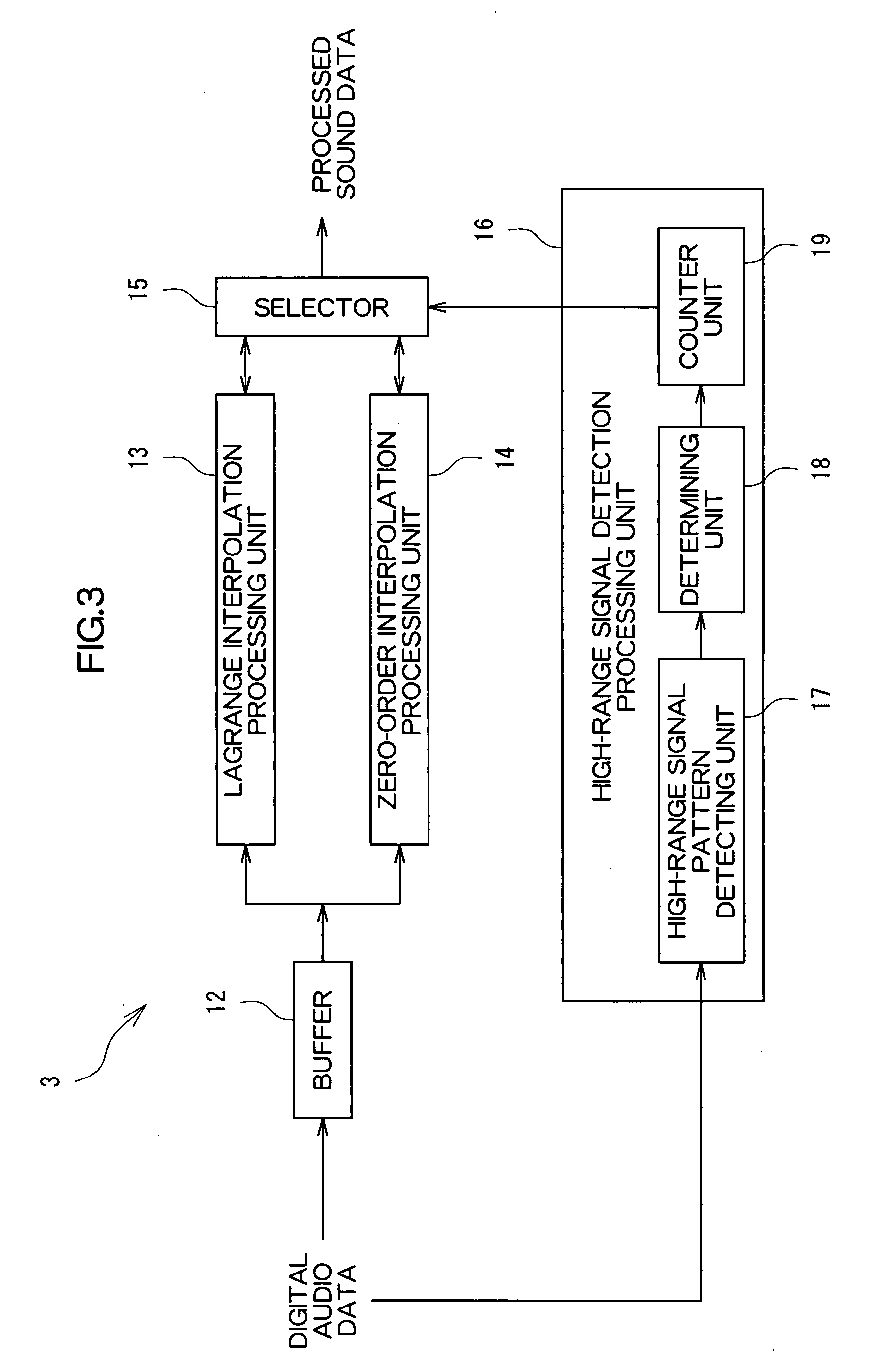
[0047]The filter circuit 3 performs filtering proces...


PUM


Abstract

The present invention relates to an audio signal output device for outputting based on a digital audio signal. A judging unit judges the frequency of reversals in polarity of the digital audio signal. A selecting unit switches an output of the audio signal output device between an output based on a first interpolated digital audio signal obtained by interpolating the digital audio signal by way of a first interpolation processing and another output based on a second interpolated digital audio signal obtained by interpolating the digital audio signal by way of a second interpolation processing in response to a judgment result made by the judging unit.

Description

TECHNICAL FIELD[0001]The present invention relates to a technique of an audio signal output device.BACKGROUND ART[0002]In audio signal output devices (for example, CD (Compact Disc) players or AV (Audio Visual) amplifiers), digital audio data is filtered by digital filters to be oversampled (interpolated) before being D / A (Digital-to-Analog) converted, and then are filtered by low-pass filters (LPFs) having high cut-off frequencies. As a result, any influence from the LPFs on amplitudes and phase characteristics of D / A-converted analog audio signals is reduced, thus improving sound quality.[0003]In general, for cases in which analog audio signals are A / D (Analog-to-Digital) converted, in order that only frequencies equal to or lower than ½ of a sampling frequency “fs” be included, the analog audio signal is filtered by an aliasing filter. For instance, with a compact disc (CD), the sampling frequency “fs” thereof is 44.1 kHz. As a consequence, such digital audio data is recorded on ...

Claims


Application Information

Patent Timeline
Patent Type & Authority Applications(United States)
IPC IPC(8): G06F17/00G10L21/0388
CPCG10L21/038G11B20/10009G11B20/10527G11B2020/10546H03M1/661G11B2020/10583H03H17/028H03H17/0294H03H17/0621G11B2020/10564H03H17/02H03H17/00G10L13/00H03G5/02
Inventor FUKUSHIMA, MITSUGI
Owner D & M HOLDINGS INC
Learn More