
High efficiency stoichiometric internal combustion engine system

a stoichiometric, internal combustion engine technology, applied in the direction of process and machine control, electrical control, instruments, etc., can solve the problems of energy waste, nitrous oxide reduction is more difficult to achieve, for example, three-way catalysts, thermodynamic losses, etc., to reduce nitrous oxide emissions.

Inactive Publication Date: 2008-11-20
DEERE & CO
View PDF3 Cites 5 Cited by
  • Summary
  • Abstract
  • Description
  • Claims
  • Application Information

AI Technical Summary

Benefits of technology

[0007]In one form, the invention is a power system including a fuel consuming internal combustion engine having at least an intake for combustion air and an exhaust for products of combustion. A positive displacement air handling device is placed in series air flow connection with the engine intake. A device is provided for controlling the air flow rate of the air handling device to maintain the air-fuel ratio of the engine at approximately a stoichiometric ratio whereby a three-way catalyst may be used to reduce nitrous oxide emissions in the exhaust of the internal combustion engine.
[0008]In another form, the invention is embodied in a method of operation of a fuel consuming air breathing compression ignition engine having an intake for air and an exhaust for products of combustion. The method includes the steps of operating the compression ignition engine and using a positive displacement air handling device in series flow connection with the engine intake to control the engine air-flow ratio to substantially stoichiometric whereby a three-way catalyst may be used to reduce nitrous oxide emissions in the exhaust of the compression ignition engine.

Problems solved by technology

While the diesel engine provides superior part-power fuel economy it has a combustion process making it more difficult to reduce the oxides of nitrogen with, for example, three-way catalyst.
The introduction of this throttling device, however simple, produces thermodynamic losses in the sense that the air into the engine is throttled and energy is wasted.

Method used


Image

  • High efficiency stoichiometric internal combustion engine system
  • High efficiency stoichiometric internal combustion engine system

Examples


Embodiment Construction

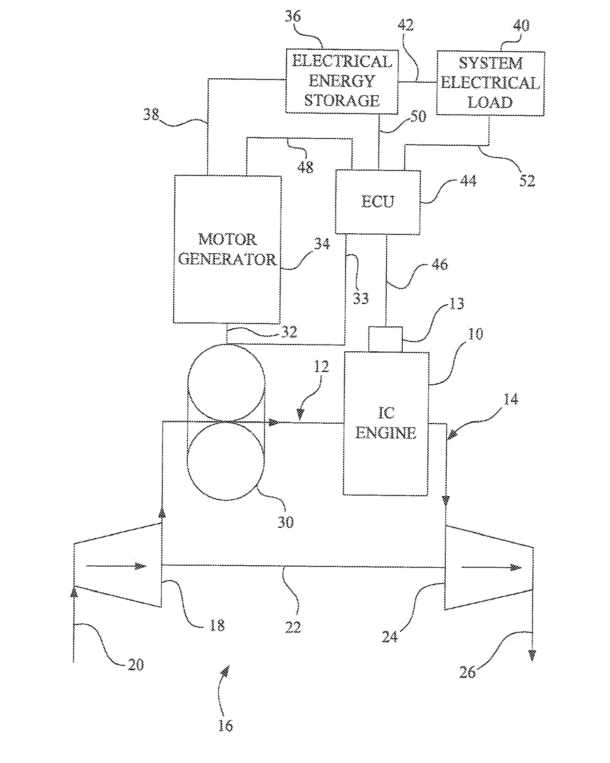
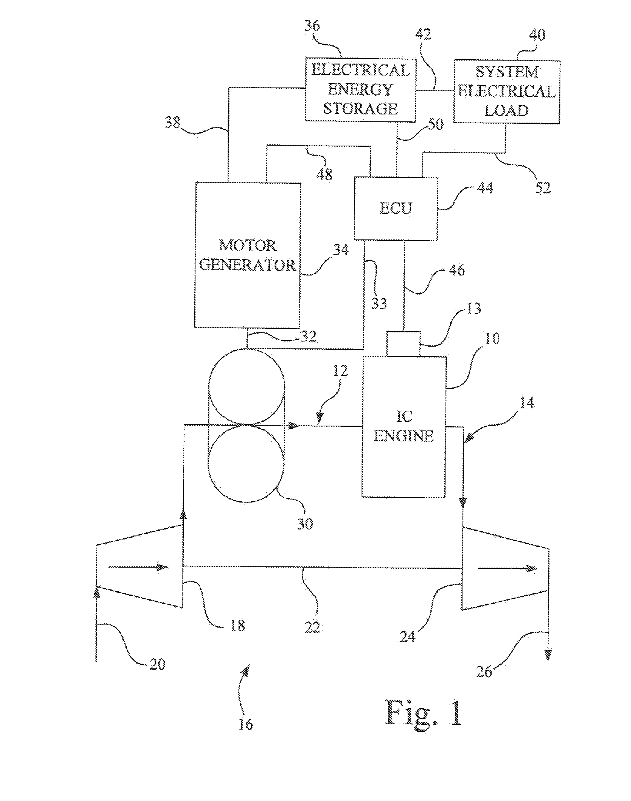
[0010]FIG. 1 shows a power system having as its foundation an air breathing, fuel consuming, internal combustion engine 10 in which a one or more pistons reciprocate within an engine block and are connected to a crankshaft for producing a rotary output. Each piston forms part of a variable volume combustion chamber that receives air for combustion from an intake system 12. The products of combustion pass through an exhaust system 14. In typical fashion, poppet valves (not shown to simplify the understanding of the invention) are actuated by cam shafts to open at the appropriate point in the cycle to permit intake of air or allow exhaust of the products of combustion. As herein shown, the internal combustion engine is a compression ignition or diesel type. This engine is usually characterized by having a significantly high compression ratio for intake air so that in the compression process, the intake air is heated to a point that it will self-combust upon the injection of a hydrocar...


PUM


Abstract

A power system including a stoichiometric compression ignition engine in which a roots blower is positioned in the air intake for the engine to control air flow. Air flow is decreased during part power conditions to maintain the air-fuel ratio in the combustion chamber of the engine at stoichiometric, thus enabling the use of inexpensive three-way catalyst to reduce oxides of nitrogen. The roots blower is connected to a motor generator so that when air flow is reduced, electrical energy is stored which is made available either to the roots blower to temporarily increase air flow or to the system electrical load and thus recapture energy that would otherwise be lost in reducing air flow.

Description

GOVERNMENT RIGHTS IN PATENT[0001]This invention was made with Government support under contract DE-FC26-05NT42416 awarded by the Department of Energy. The United States Government has certain rights in this invention.FIELD OF THE INVENTION[0002]The present invention relates to internal combustion engine systems and more specifically to engines operating at stoichiometric air fuel ratios.BACKGROUND OF THE INVENTION[0003]Internal combustion engines come in a number of forms, the most common of which are spark ignited, gasoline fueled, engines and compression ignition ignited, diesel engines. Modern spark ignited, gasoline fueled, engines utilize air, either at atmospheric or above atmospheric pressure, and mix it with fuel, through an appropriate fuel metering system, to produce a mixture in the combustion chamber that is as close to stoichiometric as possible. The stoichiometric air-fuel ratio is the mass ratio at which all the fuel and all the air are combined in the combustion proc...

Claims


Application Information

Patent Timeline
IPC IPC(8): F02D41/00
CPCF02B33/38F02B39/10F02D41/0295F02D41/1454F02D2009/0283F02D2250/32Y02T10/22Y02T10/12
Inventor WINSOR, RICHARD EDWARDCHASE, SCOTT ALLEN
Owner DEERE & CO
Learn More