

Microfabricated elastomeric valve and pump systems
a technology of elastomeric valves and micro-fabricated elastomeric valves, which is applied in the direction of multi-way valves, apparatuses with spatial temperature gradients, chemical vapor deposition coatings, etc., can solve the problems of large and complex designs, limited bulk and surface micro-machining methods, and each approach suffers from its own limitations. , to achieve the effect of small size and high speed
- Summary
- Abstract
- Description
- Claims
- Application Information
AI Technical Summary
Benefits of technology
Problems solved by technology
Method used
Image

Examples
Embodiment Construction
[0127]The present invention comprises a variety of microfabricated elastomeric structures which may be used as pumps or valves. Methods of fabricating the preferred elastomeric structures are also set forth.
[0128]Methods of Fabricating the Present Invention:
[0129]Two exemplary methods of fabricating the present invention are provided herein. It is to be understood that the present invention is not limited to fabrication by one or the other of these methods. Rather, other suitable methods of fabricating the present microstructures, including modifying the present methods, are also contemplated.
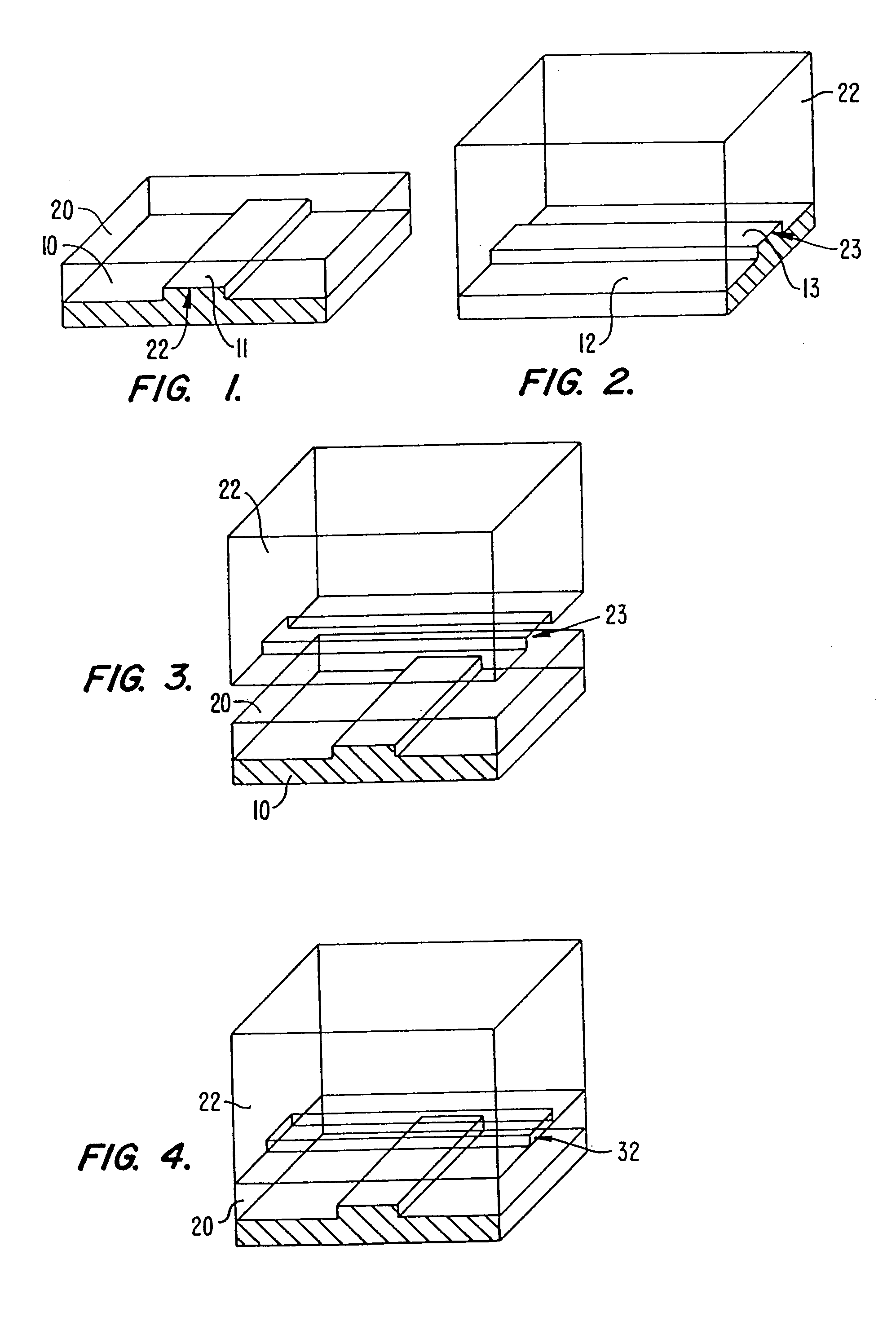
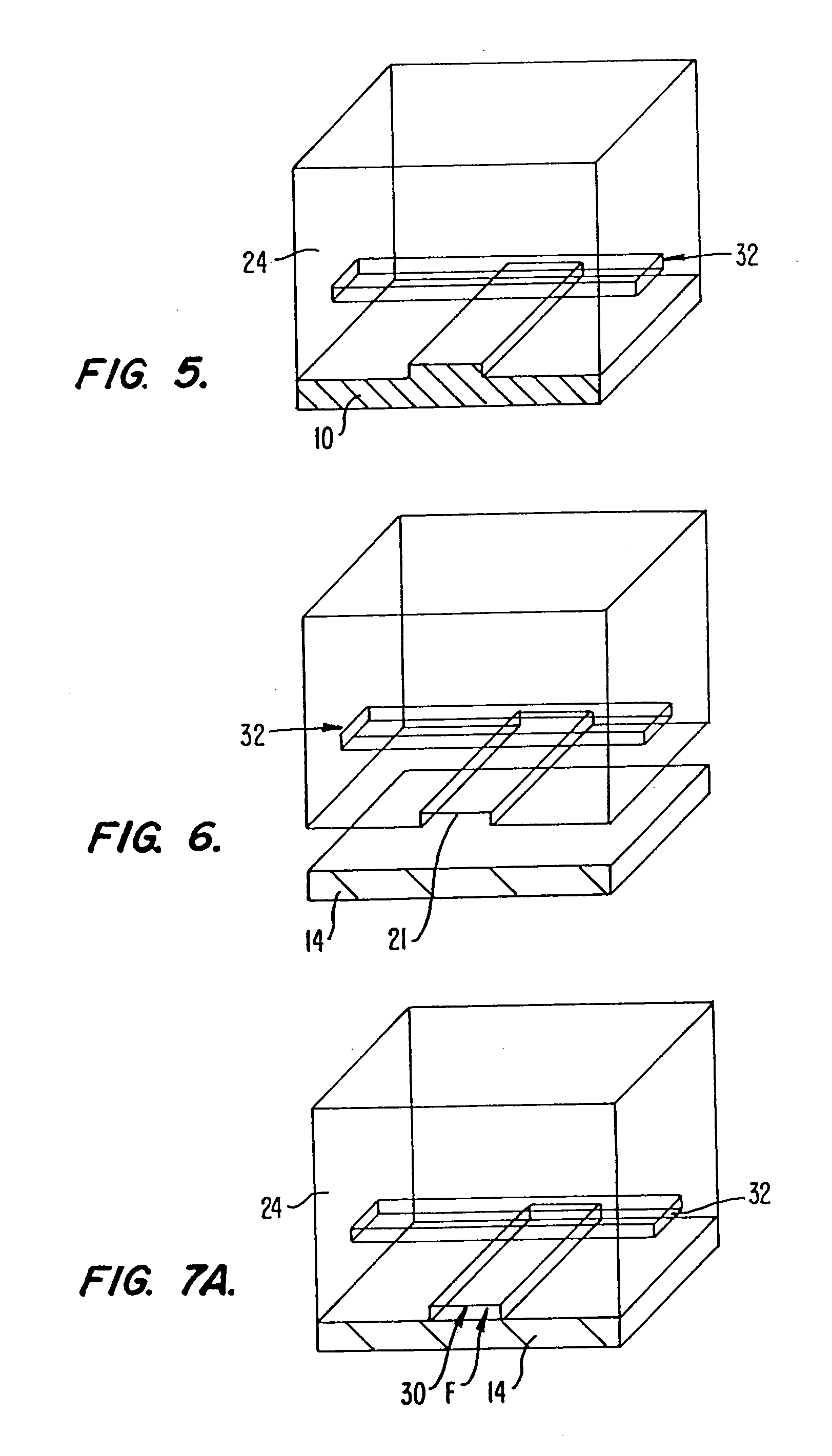
[0130]FIGS. 1 to 7B illustrate sequential steps of a first preferred method of fabricating the present microstructure, (which may be used as a pump or valve). FIGS. 8 to 18 illustrate sequential steps of a second preferred method of fabricating the present microstructure, (which also may be used as a pump or valve).
[0131]As will be explained, the preferred method of FIGS. 1 to 7B involves using...
PUM
| Property | Measurement | Unit |
|---|---|---|
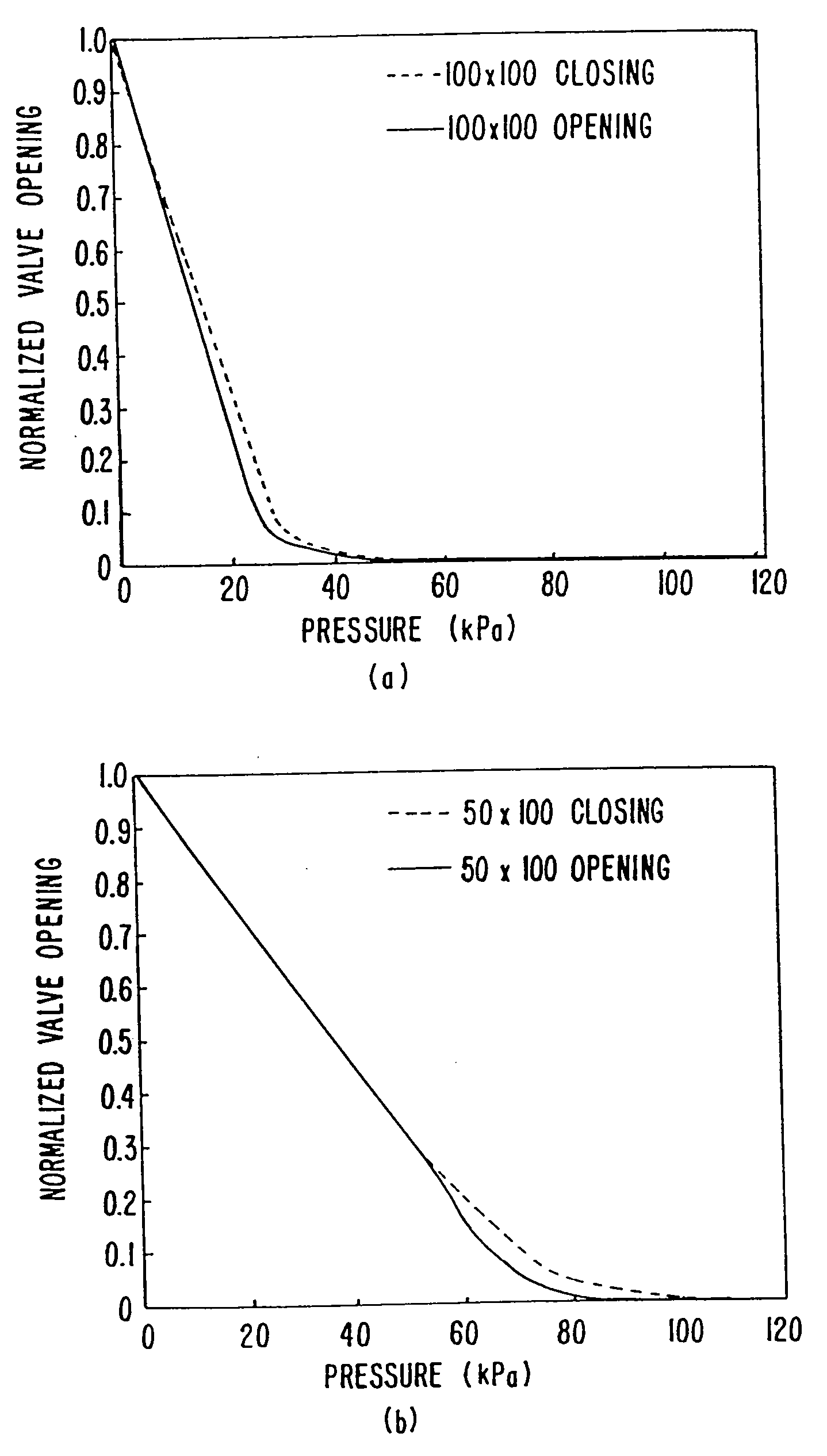
| Pressure | aaaaa | aaaaa |
| Pressure | aaaaa | aaaaa |
| Pressure | aaaaa | aaaaa |
Abstract
Description
Claims
Application Information