
Fixed cutter bit and blade for a fixed cutter bit and methods for making the same

a technology of fixed cutters and fixed blades, which is applied in the direction of drill bits, cutting machines, earth-moving drilling and mining, etc., can solve the problems of abrasive wear, bit body and other elements of earth-moving bits are subjected to many forms of wear, and the most common form of wear

Active Publication Date: 2008-11-27
KENNAMETAL INC
View PDF17 Cites 39 Cited by
  • Summary
  • Abstract
  • Description
  • Claims
  • Application Information

AI Technical Summary

Benefits of technology

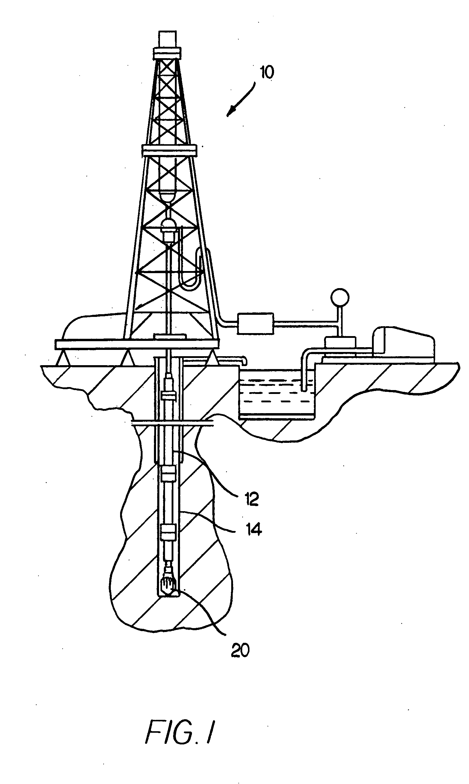
[0136]As can be appreciated, the present invention provides an improved blade, which carries cutter elements, that is affixed or attached to a tool or bit body. The tool or bit (e.g., fixed cutter bit) is useful in applications that involve impingement of the earth strata (e.g., downhole drilling, mining applications, road planning applications, concrete cutting applications, and the like). The improved blade increases the overall tool life of the tool or bit by the use of materials with improved combinations of strength, toughness, abrasion wear resistance and / or erosion wear resistance.

Problems solved by technology

The bit body and other elements of earth-boring bits are subjected to many forms of wear as they operate in the harsh down hole environment.
Among the most common form of wear is abrasive wear caused by contact with abrasive rock formations.
In addition, the drilling mud, laden with rock cuttings, causes erosive wear on the bit.
Since the blades that carry the cutter elements experience (or can experience) a significant amount of abrasive wear during the drilling operation due to the abrasive nature of a typical earth formation.
Since the blades that carry the cutter elements experience (or can experience) a significant amount of impact during the drilling operation due to the inconsistent nature of a typical earth formation in that it contains hard inclusions (e.g., rock).
During the drilling operation, the blades, which carry the cutter elements, experience (or can experience) a significant amount of erosive wear.
This erosive wear can be due to the impingement of the fluid, as well as the abrasive nature of a typical earth formation.

Method used


Image

  • Fixed cutter bit and blade for a fixed cutter bit and methods for making the same
  • Fixed cutter bit and blade for a fixed cutter bit and methods for making the same
  • Fixed cutter bit and blade for a fixed cutter bit and methods for making the same

Examples


second embodiment

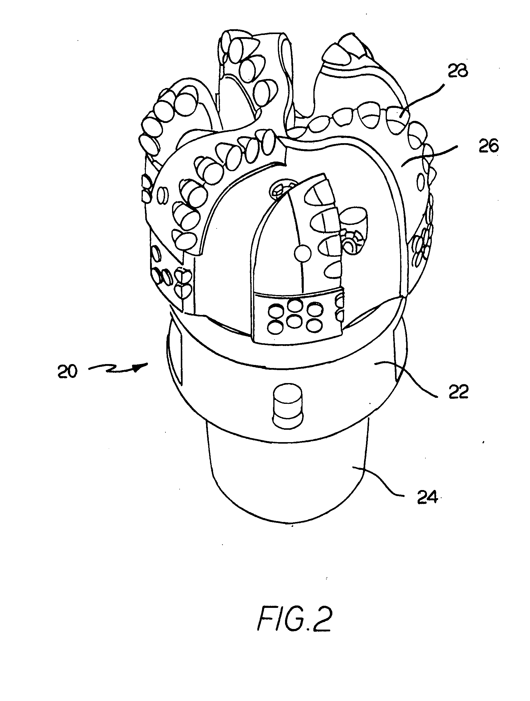
[0053]FIG. 3A is a side view of a single blade 40 from a fixed cutter bit along the lines of FIG. 2 with the PDC cutter elements removed from the blade so as to expose the grooves 42 in the blade. The blade 40 comprises a leading portion 44 and a trailing portion 46 joined to the leading portion 44.

[0054]In this specific embodiment, the leading portion 44 of the blade 40 comprises cemented carbide (e.g., cemented (cobalt) tungsten carbide) and the trailing portion 46 of the blade 40 comprises steel. The leading portion 44 and trailing portion 46 can be joined together by any one of a number of techniques including without limitation brazing techniques and infiltration techniques. Although it will be discussed in more detail hereinafter, the blade 40 is joined at the radial inward edge 48 thereto the cutter bit body by any one of a number of techniques including without limitation brazing techniques, infiltration techniques, press fitting techniques, shrink fitting techniques, weldin...

third embodiment

[0055]FIG. 3B is a side view of a single blade 50 from a fixed cutter bit along the lines of FIG. 2 with the PDC cutter elements removed from the blade so as to expose the grooves 52 in the blade 50. The blade 50 has a leading portion 54 and a trailing portion 56 that are joined together. The leading portion 54 of the blade 50 comprises steel. The trailing portion 56 of the blade 50 comprises cemented carbide (e.g., cemented (cobalt) tungsten carbide). The leading portion 54 and trailing portion 56 can be joined together by any one of a number of techniques including without limitation brazing techniques and infiltration techniques. Although it will be discussed in more detail hereinafter, the blade 50 is joined at the radial inward edge 58 thereto the cutter bit body by any one of a number of techniques including without limitation brazing techniques, infiltration techniques, press fitting techniques, shrink fitting techniques, welding techniques, and mechanical technical technique...

fourth embodiment

[0057]FIG. 4A is a side view of a single blade 60 from a fixed cutter bit along the lines of FIG. 2 with the PDC cutter elements removed from the blade 60 so as to expose the grooves 62 in the blade 60. The blade 60 has a leading portion 64 that is joined together with a trailing portion 66. In this embodiment, the leading portion 64 of the blade 60 comprises cemented carbide (e.g., cemented (cobalt) tungsten carbide) and the trailing portion 66 of the blade 60 comprises a hard component-matrix composite material. The hard component-matrix composite material will be described in more detail hereinafter. The leading portion 64 and trailing portion 66 can be joined together by any one of a number of techniques including without limitation brazing techniques and infiltration techniques. Although it will be discussed in more detail hereinafter, the blade 60 is joined at the radial inward edge 68 thereto the cutter bit body by any one of a number of techniques including without limitatio...


PUM

PropertyMeasurementUnit
melting pointaaaaaaaaaa
surface areaaaaaaaaaaa

Abstract

A blade, which is useful on a tool that impinges earth strata, that has a blade body with a leading surface. The blade body has a first portion defining at least a part of the leading surface and a second portion. The first portion is made of a first material composition and the second portion is made of a second material composition.

Description

BACKGROUND OF THE INVENTION[0001]The invention pertains to a fixed cutter bit, as well as a blade for a fixed cutter bit, and the methods for making the same, that is useful in drilling boreholes in subterranean formations such as is common in oil and gas exploration. More specifically, the invention pertains to a fixed cutter bit, as well as a blade for a fixed cutter bit, and the methods for making the same, that is useful in drilling boreholes in subterranean formations wherein the fixed cutter bit contains blades that exhibit improved wear resistance and toughness.[0002]Earth-boring bits may have fixed or rotatable cutting elements. Earth-boring bits with fixed cutting elements typically include a bit body machined from steel or fabricated by infiltrating a bed of hard particles, such as cast carbide (WC+W2C), tungsten carbide (WC), and / or sintered cemented carbide with a binder such as, for example, a copper-base alloy. Several cutting inserts are fixed to the bit body in prede...

Claims


Application Information

Patent Timeline
Patent Type & Authority Applications(United States)
IPC IPC(8): E21B10/28E21B10/12
CPCE21B10/42C22C29/16C22C29/14C22C29/06C22C26/00E21B10/62C22C29/02E21B10/55C22C2204/00E21B10/633
Inventor MAJAGI, SHIVANAND I.BITLER, JONATHAN W.
Owner KENNAMETAL INC
Learn More