
Knife bank assembly of a counter knife assembly of an integral chopper assembly of a combine harvester

a technology of combine harvester and knife bank, which is applied in the field of integrated chopper assemblies and knife bank assemblies of counter knife assemblies, can solve the problems of difficult system achievement, degree of success and satisfaction desired, and limited success of integrated chopper systems, so as to improve the versatility of operation and achieve quick and easy adjustment

Active Publication Date: 2008-11-27
BLUE LEAF I P INC
View PDF28 Cites 20 Cited by
  • Summary
  • Abstract
  • Description
  • Claims
  • Application Information

AI Technical Summary

Benefits of technology

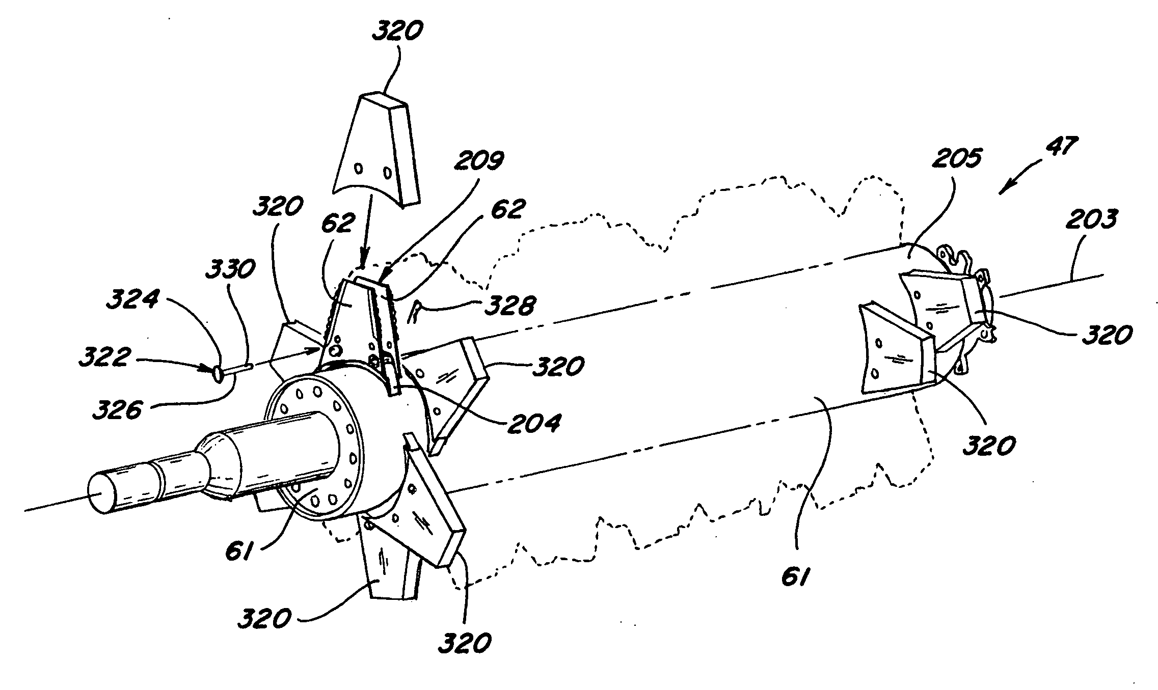
The present invention is an improved chopper assembly that includes various features and components that contribute to its overall improvement in operation and versatility. The chopper assembly includes a rotary chopper element with improved layout and arrangement of knife blade helixes, as well as an interruption plate and optional blade covers for converting the knife blades to function as beater elements instead of chopping elements. The chopper assembly also includes an improved knife bank assembly with individual removable mounts for the knife elements, making it easier to access and replace them. These features and improvements, along with other improvements and features, contribute to the improved performance of the chopper assembly.

Problems solved by technology

In general, such integral chopper systems have met with limited success, due in part to difficulties in dealing with the increase in material throughput that has been experienced over the past 10 years as machine capacities, and consequent demands upon the integral position, have increased.
More particularly, at least with respect to flail-type integral chopper systems, it has proven difficult to achieve a system that can, to the desired degrees, effectively offer and provide the dual capabilities of, in one alternative, chopping into or reducing the residue to finer pieces for spreading as such residue is transported rearwardly and, in the other alternative, more gently transporting the residue, in larger pieces, rearwardly for windrowing.
The use of flail-type elements and mountings in lieu of fixed and rigidly mounted knife blades on the rotary element has generally not resulted in the degree of success and satisfaction desired therefor, especially when such an integral chopper system has been operated as an 800 RPM flail chopper.
In such operation, the flail-type elements, due to the lack of inertia associated therewith, have sometimes, even in the absence of heavy loading, folded back along their direction of travel and caused plugging of the harvester and consequent reliability problems.
Such factor has been seen as a significant limitation to, and disadvantage of, a flail-type integral chopper as opposed to a fixed blade integral chopper.
Often, with a fixed blade integral chopper, an impact with such a foreign object, especially if relatively severe, would effect mission disabling damage to a fixed blade integral chopper system, such as by cracking or breaking either or both the rotating knife blades or the stationary counter knife elements, or even snapping off the knife blade or element or breaking off its mounting, resulting in missing knife blade components and denigrating the performance of the assembly.
The ongoing challenge has been to develop an integral chopper assembly that can offer the various advantages desired while overcoming or minimizing the disadvantages that have been encountered with the prior art systems.

Method used


Image

  • Knife bank assembly of a counter knife assembly of an integral chopper assembly of a combine harvester
  • Knife bank assembly of a counter knife assembly of an integral chopper assembly of a combine harvester
  • Knife bank assembly of a counter knife assembly of an integral chopper assembly of a combine harvester

Examples


Embodiment Construction

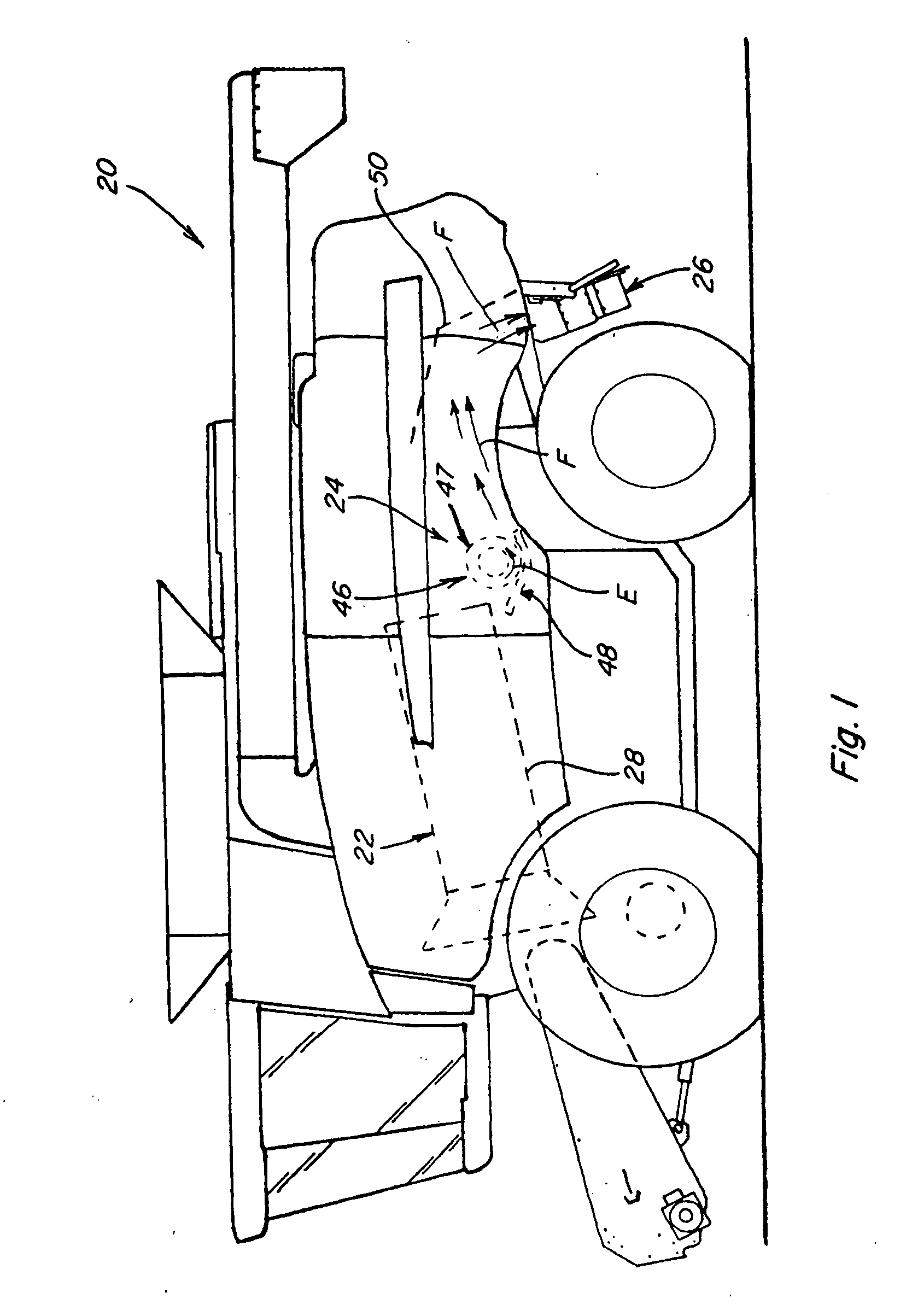
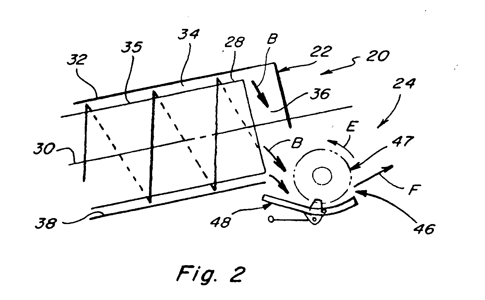
[0053]Referring now to the drawings, wherein preferred embodiments of an improved integral chopper assembly that includes the present invention are shown, wherein like numerals refer to like items, wherein certain elements and features may be labeled or marked on a representative basis without each like element or feature necessarily being individually shown, labeled, or marked, and wherein certain elements are labeled and marked in only some, but not all, of the drawing figures, FIGS. 1 and 2 depict a representative agricultural combine 20 that includes a longitudinally axially arranged threshing system 22 and a crop residue treatment and distribution system 24 with a crop residue spreader 26, all of which, except for the improved integral chopper system that is the subject hereof and which is included within the crop residue and distribution system 24, are of well known construction and operation.

[0054]As can be generally and essentially observed from a review and study of FIGS. 1...


PUM

PropertyMeasurementUnit
widthaaaaaaaaaa
angleaaaaaaaaaa
angleaaaaaaaaaa

Abstract

An improved knife bank assembly of a counter knife assembly of an integral chopper assembly of a combine harvester that includes an elongated bracket member that extends between opposed knife bank end plates and has a plurality of spaced retainment mounts securable therealong, with at least one, and preferably two, knife blades being removably connectable to each retainment mount in a side-by-side arrangement. The bracket member is preferably mounted to a shaft member that extends between concave pan side plates to be slidable along such shaft member to permit adjustable positioning of the knife bank assembly and the knife elements thereof relative to the slots of the grate portion, and the retainment mounts are preferably removably securable to the bracket member. The knife elements are removably connectable to the retainment mounts at first and second space mounting points, preferably in such a way that the knife elements are maintained in an extended position by application of a biasing force at the second mounting point but are rotatable about the first mounting point to a displaced or relaxed position if a sufficient force is applied to the leading edge of the knife element to overcome the biasing force.

Description

[0001]This application claims the benefit of U.S. Provisional Application No. 60 / 931,418, filed May 23, 2007.TECHNICAL FIELD[0002]This invention relates generally to agricultural harvesting combines and machines and to straw and residue chopping systems therewith, especially integral chopper assemblies that have a rotary chopper element or portion and an associated counter knife assembly positioned generally parallel thereto, and more particularly to a knife bank assembly of the counter knife assembly and components thereof, especially retainment mounts for the knife elements that permit the knife elements of the knife bank assembly to be both individually replaceable within the knife bank assembly and also displaceable under extreme loading to prevent damage thereto, and a mounting of the knife bank assembly to permit adjustability of the knife bank relative to the grate portion of the chopper grate assembly so as to make certain alignment tasks easier.BACKGROUND ART[0003]In the op...

Claims


Application Information

Patent Timeline
Patent Type & Authority Applications(United States)
IPC IPC(8): B02C18/14B02C13/00
CPCA01F12/40Y10T29/49902Y10T29/49895Y10T29/53961Y10T29/53974Y10T29/49233
Inventor BENES, JASON M.LAUWERS, ANDREW V.ISAAC, NATHAN E.FARLEY, HERBERT M.WAGNER, BRADLEY J.RICKETTS, JONATHAN E.WARD, KEVIN W.
Owner BLUE LEAF I P INC
Learn More