Time-Of-Flight Mass Spectrometer

Inactive Publication Date: 2008-11-27
NAT INST OF ADVANCED IND SCI & TECH
View PDF6 Cites 31 Cited by
  • Summary
  • Abstract
  • Description
  • Claims
  • Application Information

AI Technical Summary

Benefits of technology

[0033]The present invention, by having the aforedescribed constitution, can realize both effects of a conventional accelerating portion and ion lens system with only a repeller electrode and an extractor electrode.

Problems solved by technology

However, since the ion trajectory spreads outs after passing through the pin hole in this art, a lens system is required to make the ions reach the detector.

Method used


Image

  • Time-Of-Flight Mass Spectrometer
  • Time-Of-Flight Mass Spectrometer
  • Time-Of-Flight Mass Spectrometer

Examples


first embodiment

[0087]Hereinbelow, an embodiment of the present invention is described with reference to the drawings, but the present invention is not limited thereto. Also, in order to simplify the description, a case is described in which a neutral particle that is introduced from outside of the accelerating portion being ionized by a laser into a monovalent cation, but that is introduced may also be an ion.

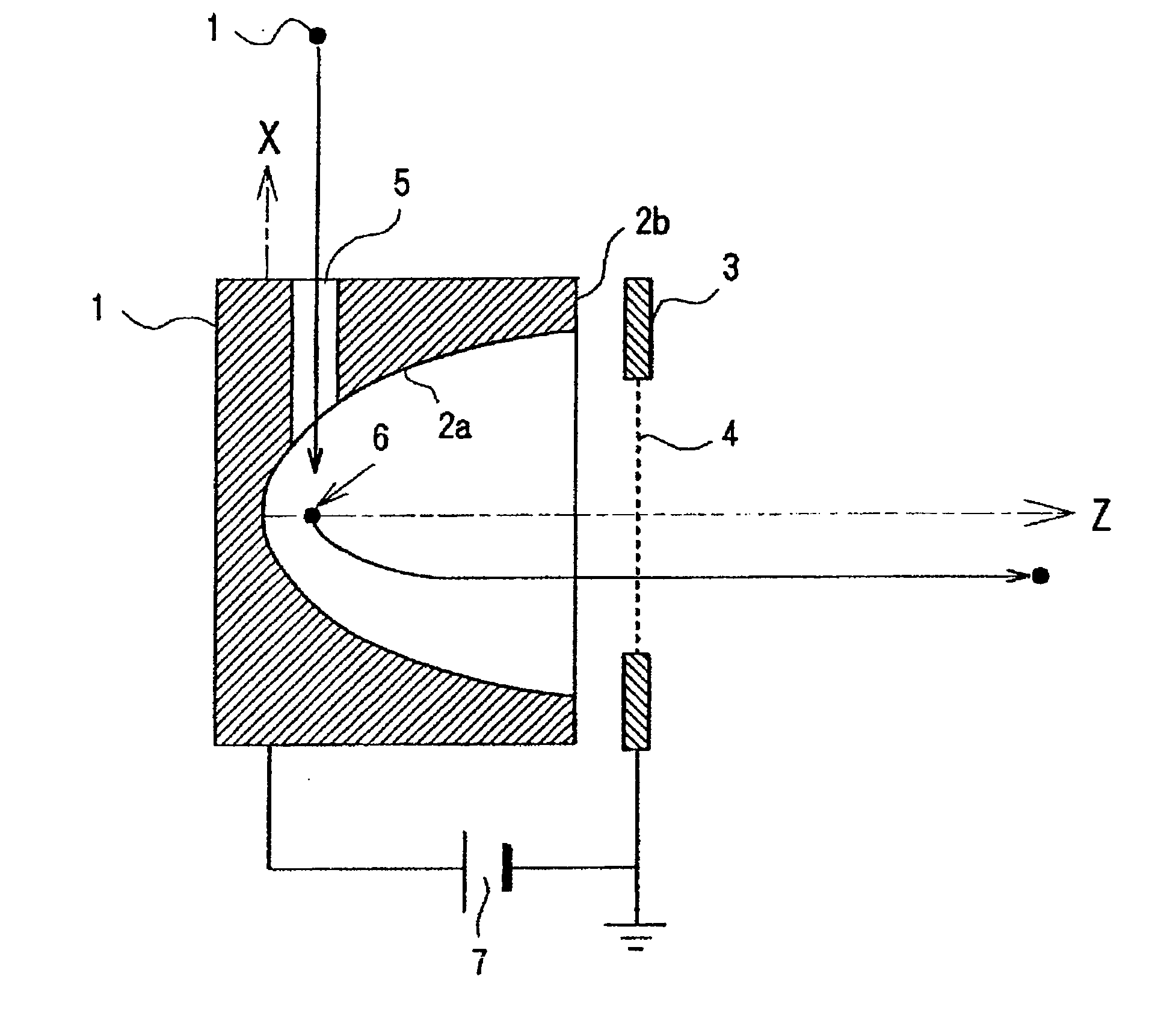
[0088]FIG. 1 is a drawing showing an example of the accelerating portion in the time-of-flight mass spectrometer of the present invention. Here, the direction of introducing a neutral particle 1, which is the object of measurement, is the X axis. The neutral particle 1 is ionized by a laser at an acceleration start position 6, and the resulting ion 1 is accelerated in a Z-axis direction that is perpendicular to the X axis by a repeller electrode 2 shown in a vertical cross-sectional view. The Y axis is a direction perpendicular to both the X axis and the Z axis. An extractor electrode 3 is pr...

second embodiment

[0110]As another embodiment of the present invention, an equivalent effect as the aforedescribed embodiment is obtainable with a repeller electrode that is constituted by a plurality of electrodes instead of being formed by one piece, and making an equipotential surface in the vicinity of the electrode substantially a paraboloid shape. In this embodiment, a drawing explaining an example of the accelerating portion is shown in FIG. 18, and the calculation result of the electric field and the ion trajectory of the accelerating portion are shown in FIG. 19.

[0111]FIG. 18 is a vertical cross-sectional view of the accelerator portion similar to FIG. 1. The front end portion of the repeller electrode is constituted by a plurality of hollow disc-shaped electrodes 2c. Also, the other reference numerals denote portions identical to those shown in FIG. 1. Here, applying a voltage from a power source 7 to the repeller electrode 2 generates an electric field between the repeller electrode 2 and ...


PUM


Abstract

A time-of-flight mass spectrometer comprising an accelerating portion that includes a repeller electrode and an extractor electrode, in which an inner surface on the extractor electrode side of the repeller electrode has a curved shape, the extractor electrode is a flat plate with a hole in the center or a plate structure including a mesh structure, and the accelerating portion converges a distribution of times of flight accompanying deviations in the acceleration start position of ions and also performs trajectory control by correcting a distribution of the introduction energy of ions. In accordance with the above-described structure, it is possible to realize both functions of a conventional accelerating portion and ion lens system with only an accelerating portion and it is possible to simplify and reduce the size of the time-of-flight mass spectrometer.

Description

TECHNICAL FIELD[0001]The present invention relates to a mass spectrometer that analyses the mass of particles and ions, and particularly relates to a time-of-flight mass spectrometer.BACKGROUND ART[0002]A conventional time-of-flight mass spectrometer accelerates ions by an electric field in an accelerating portion and then, by making the ions fly a certain distance, measures the time of flight until they reach a detector. Since the time of flight is proportional to the ratio of mass to electrical charge, it is possible to determine the mass from measurement of the time of flight. Note that in some cases an electric field lens or reflecting electric field (reflector) or the like is disposed in the path from the accelerating portion to the detector.[0003]The ion accelerating portion that is used in conventional time-of-flight mass spectrometers is constituted by a repeller electrode of a flat plate or of a plate structure including a mesh structure, and a extractor electrode of a flat...

Claims


Application Information

Patent Timeline
Patent Type & Authority Applications(United States)
IPC IPC(8): H01J49/40
CPCH01J49/401
Inventor SAITO, NAOAKIOHKUBO, MASATAKAKOYAMA, KAZUYOSHIMIURA, EISUKE
Owner NAT INST OF ADVANCED IND SCI & TECH
Why Eureka
Try Eureka