Constant gain amplifier system with positive and negative feedback

Inactive Publication Date: 2008-11-27
MIROW FRED A
View PDF2 Cites 12 Cited by
  • Summary
  • Abstract
  • Description
  • Claims
  • Application Information

AI Technical Summary

Benefits of technology

[0007]A further objective of the invention to provide circuits that are less susceptible to process v

Problems solved by technology

A major problem in such systems has been that to maintain amplifier stability the amplifier

Method used


Image

  • Constant gain amplifier system with positive and negative feedback
  • Constant gain amplifier system with positive and negative feedback
  • Constant gain amplifier system with positive and negative feedback

Examples


Embodiment Construction

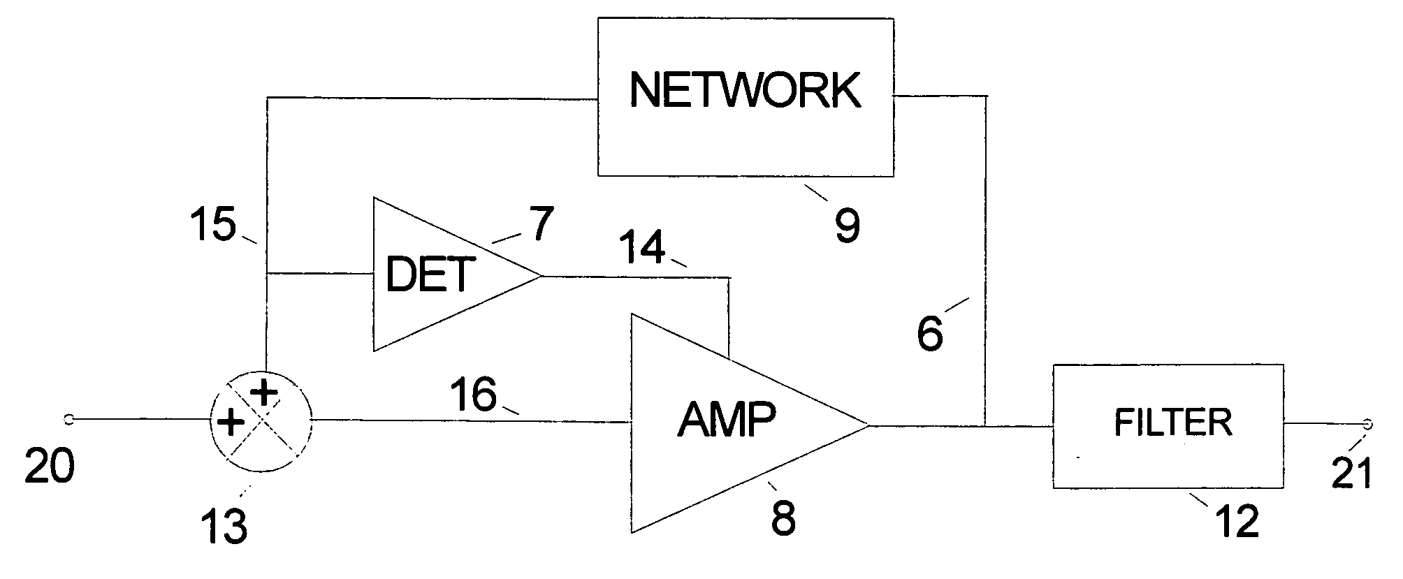
[0027]An embodiment of the invention is shown in FIG. 1. The constant gain amplifier system 1 comprising network 9, detector 7, signal combiner 13, amplifier 8, filter 12, input terminal 20 and output terminal 21. The output of network 9 on line 15 is connected to the input of detector 7 and also to a input to signal combiner 13. The other input of signal combiner 13 is connected to input terminal 20. Signal combiner 13 provides a output signal that is the sum of it's two input signals on line 16 to the input of amplifier 8. Amplifier 8 receives signals to it's gain control input from the output of detector 7 on line 14. The output of amplifier 8 is on line 6 which is connected to the inputs of filter 12 and network 9.

[0028]Network 9, signal combiner 13, amplifier 8, form a positive feedback loop which oscillates. The signal path between input terminal 20 and output terminal 21 is through signal combiner 13, amplifier 8, and filter 12.

[0029]Amplifier 8 amplifies the signal applied t...


PUM


Abstract

Constant and accurate signal gain systems based on controlling oscillator loop gain. A constant gain positive feedback network and an amplifier form an oscillator. Only when the oscillator loop gain is at least one does the oscillator produces an AC signal. Negative feedback of the oscillator's AC signal level is used to keep the loop gain close to or at the value of one by controlling the loop gain of the oscillator circuit. By maintaining the loop gain of the oscillator circuit substantially constant the signal gain is also maintained substantially constant.

Description

CROSS-REFERENCE TO RELATED APPLICATIONS[0001]The benefits of filing this invention as Provisional application for patent “Constant gain amplifier system with positive and negative feedback”, U.S. PTO #60 / 931,907 filed May 26, 2007 by Fred Mirow are claimed.BACKGROUND OF THE INVENTION[0002]This invention relates to systems for providing a constant and accurate signal gain with relatively wide bandwidth based on controlled oscillator loop gain and is described. The constant gain positive feedback network combined with an amplifier forms an oscillator. Only when the oscillator loop gain is at least one does the oscillator produces an AC signal. Negative feedback of the oscillator's AC signal level is used to control the loop gain of the oscillator circuit, keeping the loop gain close to or at one. By maintaining the loop gain of the oscillator circuit substantially constant, the signal gain of the amplifier is maintained substantially constant with the gain primarily set by the positiv...

Claims


Application Information

Patent Timeline
IPC IPC(8): H03G3/30
CPCH03F1/34H03F1/42H03F2200/36H03G3/00H03G3/20
Inventor MIROW, FRED A.
Owner MIROW FRED A
Why Eureka
Try Eureka