Differential amplifier

a technology of amplifiers and amplifiers, applied in the field of differential amplifiers, can solve the problems of increasing element area, increasing cost, reducing bandwidth, etc., and achieve the effect of reducing circuit cost, increasing speed, and decreasing area

Inactive Publication Date: 2008-11-27
ADVANTEST CORP
View PDF4 Cites 3 Cited by
  • Summary
  • Abstract
  • Description
  • Claims
  • Application Information

AI Technical Summary

Benefits of technology

[0018]The differential amplifier in a certain embodiment may be monolithically integrated on one semiconductor substrate and may be configured using a low voltage process. As described above, since voltage applied to the input different...

Problems solved by technology

As a result, the transistors M1 and M2 of the input differential pair 10 must be configured using high voltage ele...

Method used


Image

  • Differential amplifier
  • Differential amplifier
  • Differential amplifier

Examples


Embodiment Construction

[0025]The invention will now be described based on preferred embodiments which do not intend to limit the scope of the present invention but exemplify the invention. All of the features and the combinations thereof described in the embodiment are not necessarily essential to the invention.

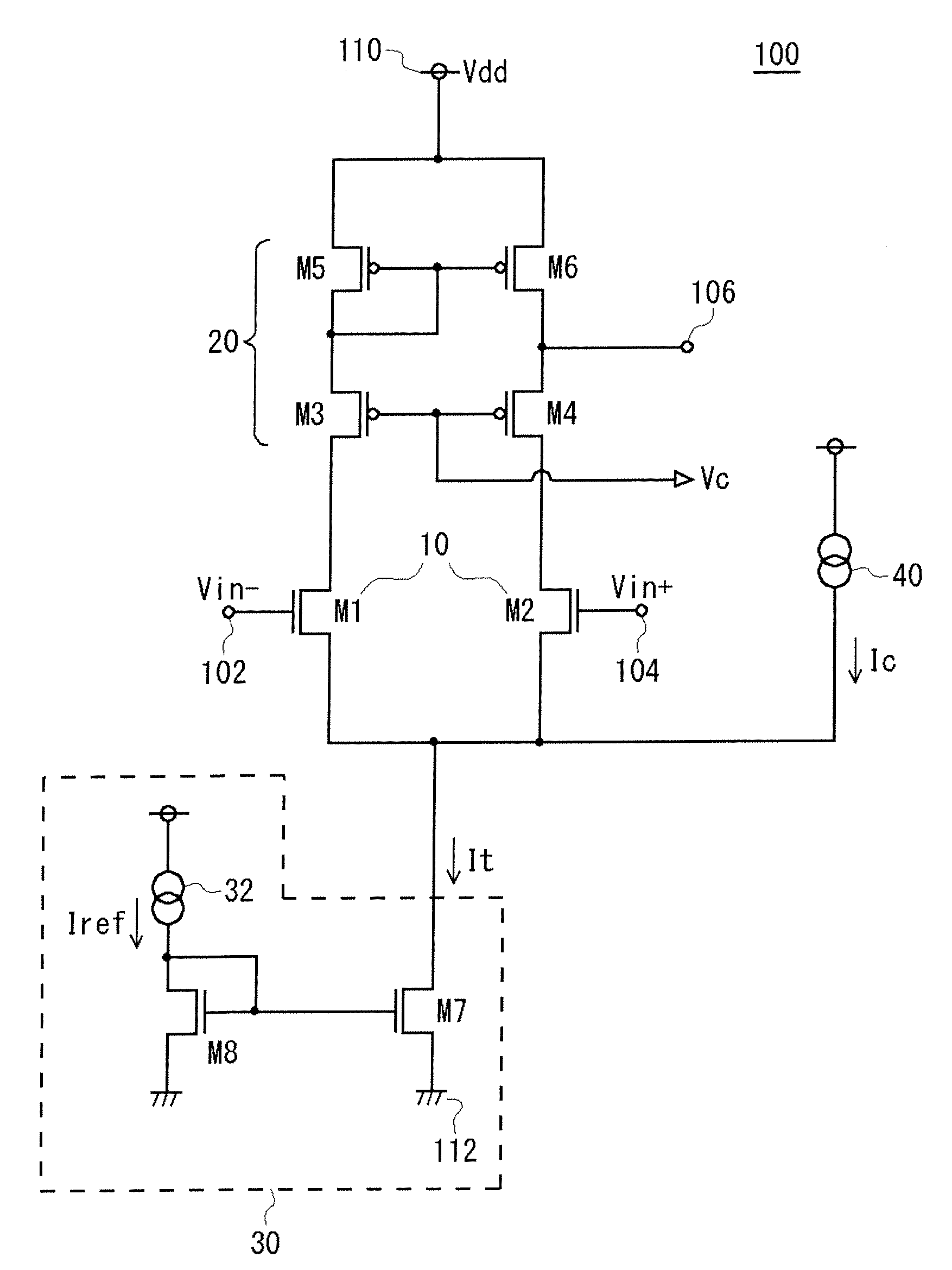
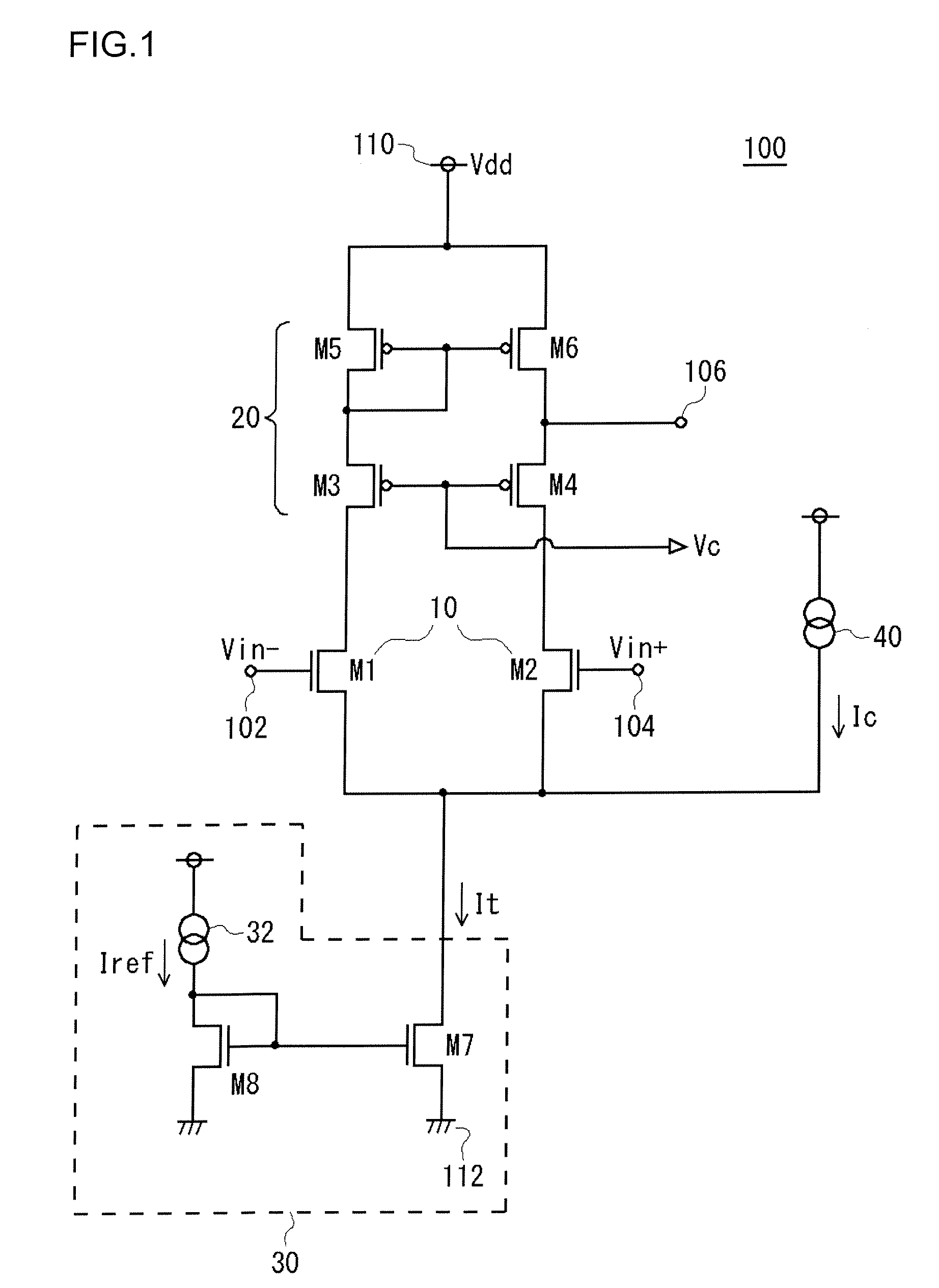
[0026]FIG. 1 is a circuit diagram showing a configuration of a differential amplifier 100 according to an embodiment. In the differential amplifier 100, signals Vin− and Vin+ inputted to an inverting input terminal 102 and a noninverting input terminal 104 are differentially amplified to be outputted from an output terminal 106.

[0027]The amplifier 100 is provided with an input differential pair 10, a cascode current mirror circuit 20, a tail current source 30, and a constant current source 40.

[0028]The input differential pair includes a first transistor M1 whose gate is connected to the inverting input terminal 102, and a second transistor M2 whose gate is connected to the noninverting input termin...


PUM


Abstract

A cascode current mirror circuit is connected as an active load to the input differential pair. A tail current source supplies a tail current to the input differential pair. A constant current source is connected in parallel with the input differential pair, and supplies a constant current to the tail current source. The constant current supplied by the constant current source is set to a value at which a transistor is not cut off.

Description

CLAIM OF PRIORITY[0001]This Application claims foreign priority from Japanese Application No. 2007-132092, filed on May 17, 2007.BACKGROUND OF INVENTION[0002]1. Field of the Invention[0003]The present invention relates to a differential amplifier.[0004]2. Description of the Related Art[0005]Differential amplifiers, and operational amplifiers or comparators that make use of differential amplifiers (referred to generically below simply as differential amplifiers) are widely used in all types of applications as basic circuits forming electronic circuits. In general a differential amplifier includes an input differential pair, a current mirror circuit or a resistor pair, which acts as a load on the input differential pair, and a tail current source which supplies a tail current to the input differential pair.[0006]In order to hold constant a drain-source voltage of a transistor of the input differential pair of the differential amplifier (or a collector-emitter voltage; below, no partic...

Claims


Application Information

Patent Timeline
IPC IPC(8): H03F3/45
CPCH03F3/45188H03F2203/45244H03F2203/45466
Inventor SHIMIZU, TAKAHIKO
Owner ADVANTEST CORP
Why Eureka
Try Eureka