[0012]Increasing the amount of EGR gas flowing through the
high pressure EGR passage reduces the amount of
fresh air drawn into the
internal combustion engine. Thus, during deceleration of the vehicle, for example, the temperature of the exhaust gas from the internal
combustion engine decreases, but if the amount of EGR gas flowing through the high pressure EGR passage is increased, the amount of exhaust gas flowing through the exhaust gas control catalyst decreases, which makes it possible to suppress a decrease in temperature of the exhaust gas control catalyst.
[0013]Further, reducing the amount of EGR gas flowing through the high pressure EGR passage increases the amount of
fresh air drawn into the internal
combustion engine. Therefore, the amount of exhaust gas flowing through the exhaust gas control catalyst increases. Also, during deceleration of the vehicle, for example, the temperature of the exhaust gas from the internal
combustion engine decreases. Therefore, reducing the amount of EGR gas flowing through the high pressure EGR passage results in more low temperature exhaust gas flowing through the exhaust gas control catalyst. Accordingly, the temperature of the exhaust gas control catalyst can be reduced, thereby making it possible to suppress overheating of the exhaust gas control catalyst.
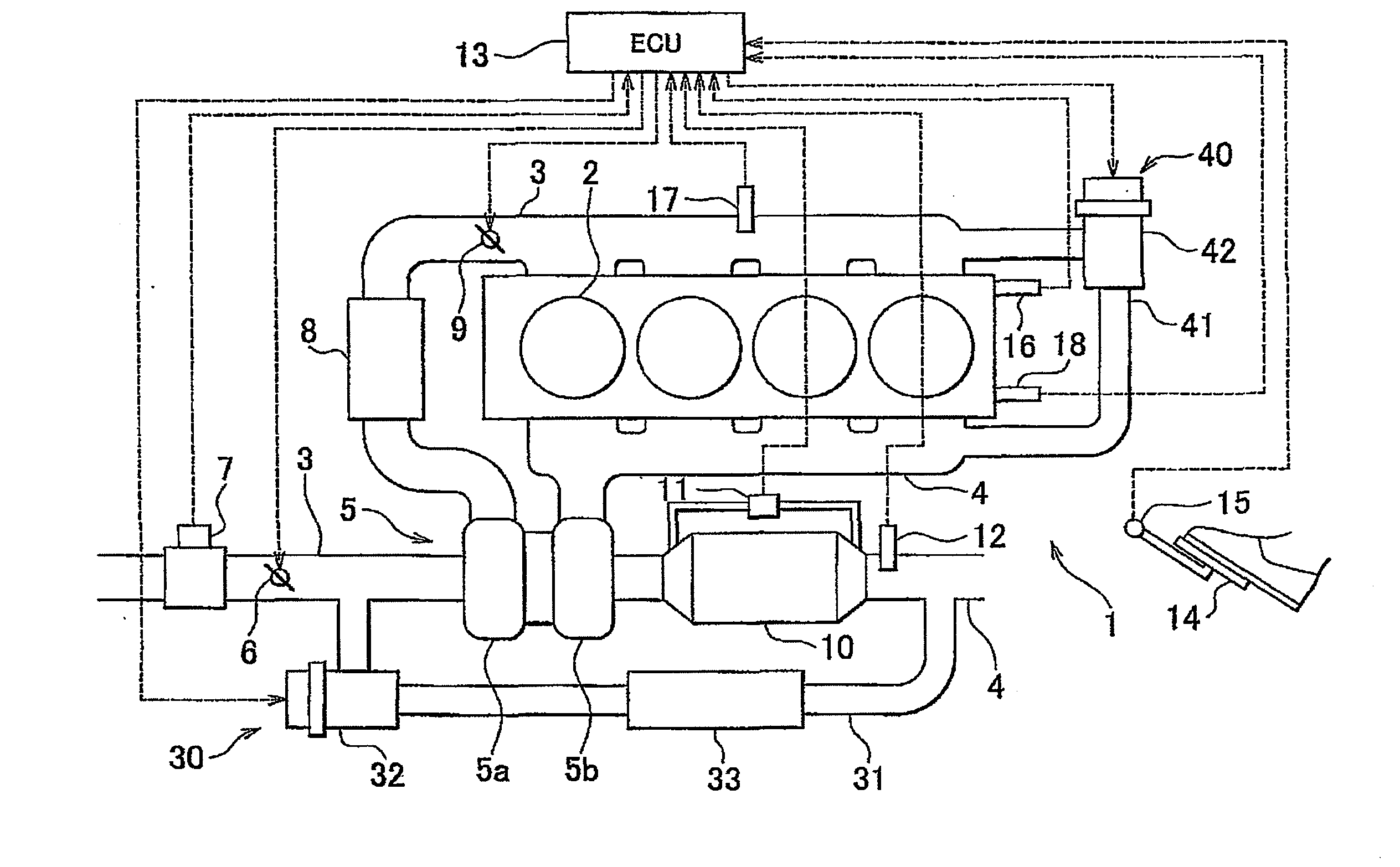
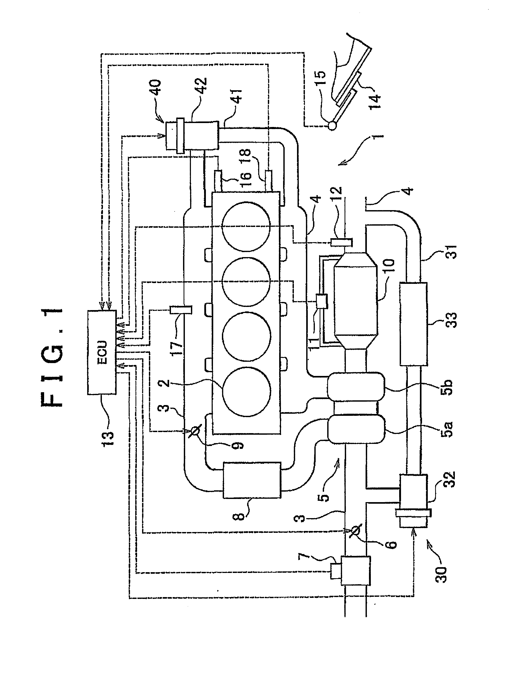
[0014]However, if when attempting to suppress a decrease in temperature of the exhaust gas control catalyst the amount of EGR gas flowing through the high pressure EGR passage is increased too much, the energy that rotates the
turbocharger decreases a corresponding amount which results in a slower increase in boost pressure during the next acceleration. On the other hand, if the amount of EGR gas flowing through the low pressure EGR passage is increased, the exhaust gas which has passed through the exhaust gas control catalyst and thus increased in temperature is drawn in as EGR gas. As a result, the temperature of the intake air increases so a decrease in the temperature of the exhaust gas can be suppressed. Accordingly, the temperature of the exhaust gas control catalyst can be maintained. That is, the temperature of the exhaust gas control catalyst can be maintained by simultaneously increasing the amounts of EGR gas flowing through the low pressure EGR passage and the high pressure EGR passage.
[0015]Also, according to a second aspect of the invention, in the first aspect, the EGR gas amount changing means simultaneously changes the amounts of EGR gas flowing through the low pressure EGR passage and the high pressure EGR passage to maintain a speed of the
turbocharger. Increasing the amount of EGR gas flowing through the low pressure EGR passage increases the amount of exhaust gas that flows through the turbine. As a result, a drop in speed of the turbocharger can be suppressed so the speed of the turbocharger can be kept within the
target range. At the same time, having EGR gas pass through the high pressure EGR passage enables the temperature of the exhaust gas control catalyst to be maintained. That is, simultaneously increasing the amounts of EGR gas flowing through the low pressure EGR passage and the high pressure EGR passage enables both the temperature of the exhaust gas control catalyst and the speed of the turbocharger to be maintained. In addition, EGR gas can be supplied while inhibiting a drop in output of the internal combustion engine so the generation of
NOx can be suppressed.
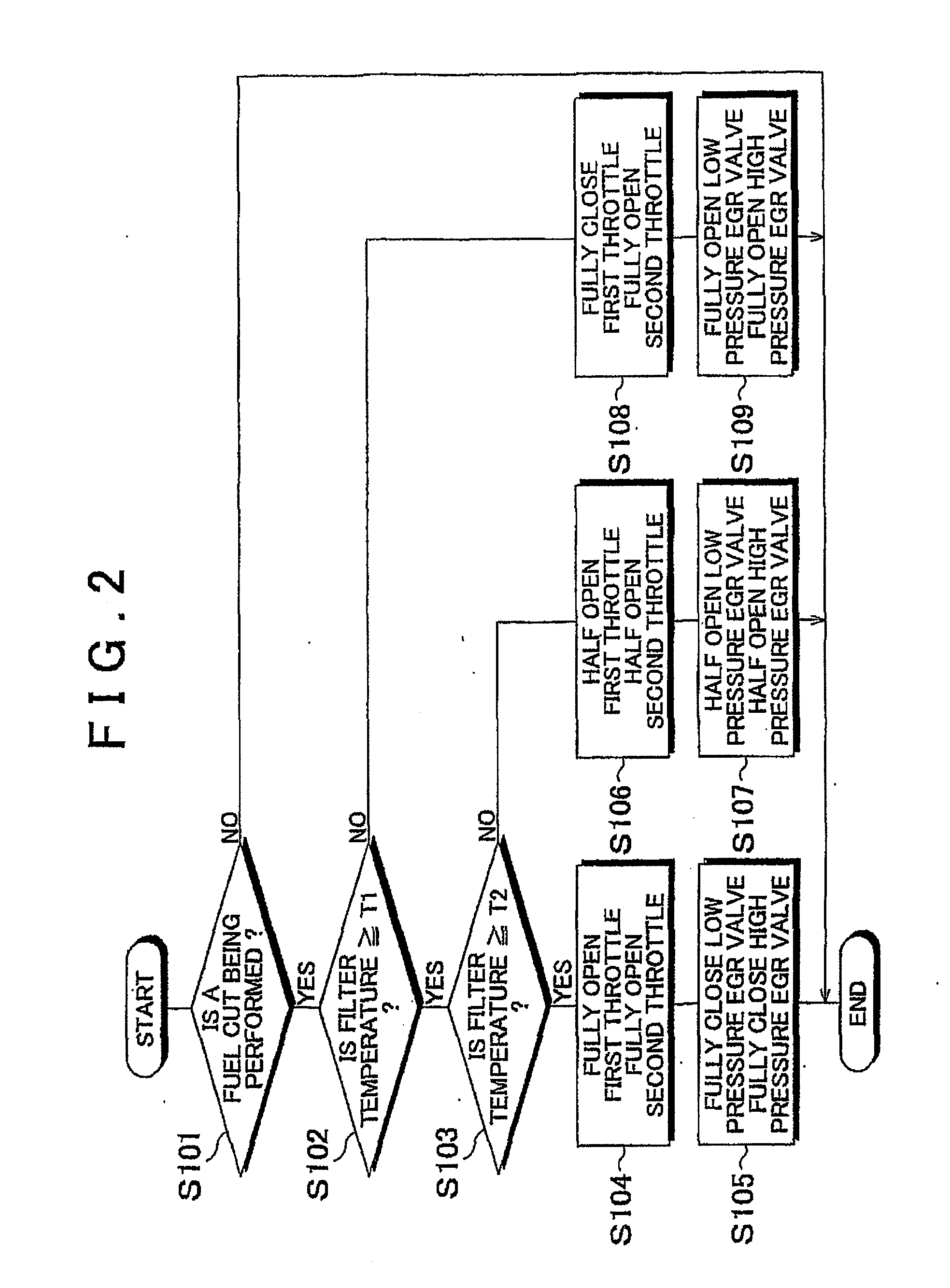
[0016]According to a third aspect of the invention, in the first or second aspect, when the temperature of the exhaust gas control catalyst is within the
target range or below the target range, the amounts of EGR gas flowing through the low pressure EGR passage and the high pressure EGR passage are increased more so than when the temperature of the exhaust gas control catalyst is above the target range. Increasing the amounts of EGR gas flowing through the low pressure EGR passage and the high pressure EGR passage reduces the amount of exhaust gas that flows through the exhaust gas control catalyst. Reducing the amount of exhaust gas that flows through the exhaust gas control catalyst during a fuel
cut, for example, enables a drop in temperature of the exhaust gas control catalyst to be suppressed. That is, increasing the amounts of EGR gas flowing through the low pressure EGR passage and the high pressure EGR passage more when the temperature of the exhaust gas control catalyst is within the target range or below the target range than when the temperature of the exhaust gas control catalyst is above the target range not only enables EGR gas of an amount appropriate for maintaining the temperature of the exhaust gas control catalyst to be supplied, but also enables EGR gas of an amount appropriate for maintaining the speed of the turbocharger to be supplied.
[0021]Regarding this point, when the vehicle is decelerating or the internal combustion engine is idling, the low pressure EGR valve and the high pressure EGR valve both open a predetermined amount. Based on the amount of
fresh air drawn into the internal combustion engine at this time, it is then possible to learn correct (i.e., correct through learning) the relationship between the amount of EGR gas flowing through the low pressure EGR passage and the opening amount of the low pressure EGR valve, or the relationship between the amount of EGR gas flowing through the high pressure EGR passage and the opening amount of the high pressure EGR valve. That is, it is possible to separately learn correct the relationship between the amount of EGR gas flowing through the low pressure EGR passage and the opening amount of the low pressure EGR valve, and the relationship between the amount of EGR gas flowing through the high pressure EGR passage and the opening amount of the high pressure EGR valve. Accordingly, the affect from the adhered
soot and the like can be reduced. At this time, because the opening amount of one EGR valve affects the amount of EGR gas flowing through the other EGR valve, the opening amount of one EGR valve can be fixed in the fully closed position, while the opening amount of the other EGR valve can be fixed in the fully open position, for example, and this other EGR valve side can be learn corrected. For example, fully closing one EGR valve makes it possible to learn correct the affect of
soot or the like in the EGR passage in which the other EGR valve is provided without being effected by the soot or the like in the EGR passage in which the one EGR valve is provided. That is, when setting both the low pressure EGR valve and the high pressure EGR valve to predetermined opening amounts, the low pressure EGR valve and the high pressure EGR valve can be set to different predetermined opening amounts.

