Time to Digital Converting Circuit and Pressure Sensing Device Using the Same

a digital conversion circuit and time-to-digital technology, applied in the direction of code conversion, fluid pressure measurement, instruments, etc., can solve the problems of difficult application of voltage-to-digital converting circuit to highly integrated circuits such as the soc, mis-operation and rapid degradation of the voltage-to-digital converting circuit performance, etc., to achieve the effect of reducing the size of the time-to-digital converting circui

Active Publication Date: 2008-12-04
ATLAB INC
View PDF7 Cites 23 Cited by
  • Summary
  • Abstract
  • Description
  • Claims
  • Application Information

AI Technical Summary

Benefits of technology

[0031]According to the present invention as described above, a time-to-digital converting circuit varies a delay time of a sensing signal depending on external stimulus strength and then generates digital data in respo

Problems solved by technology

Accordingly, when the conventional voltage-to-digital converting circuit is applied to the highly integrated SoC, the voltage generation unit 3 may not generate the voltage having the sufficient magnitude and capacity, so that performance of the voltage-to-digital converting circuit may be rapidly degraded, and mis-operation may occur in the voltage-to-digital converting circuit in the worst case.
That is, the conventional voltag

Method used


Image

  • Time to Digital Converting Circuit and Pressure Sensing Device Using the Same
  • Time to Digital Converting Circuit and Pressure Sensing Device Using the Same
  • Time to Digital Converting Circuit and Pressure Sensing Device Using the Same

Examples


first embodiment

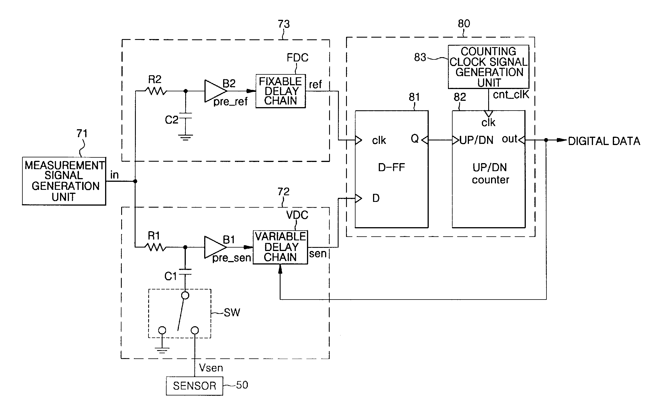
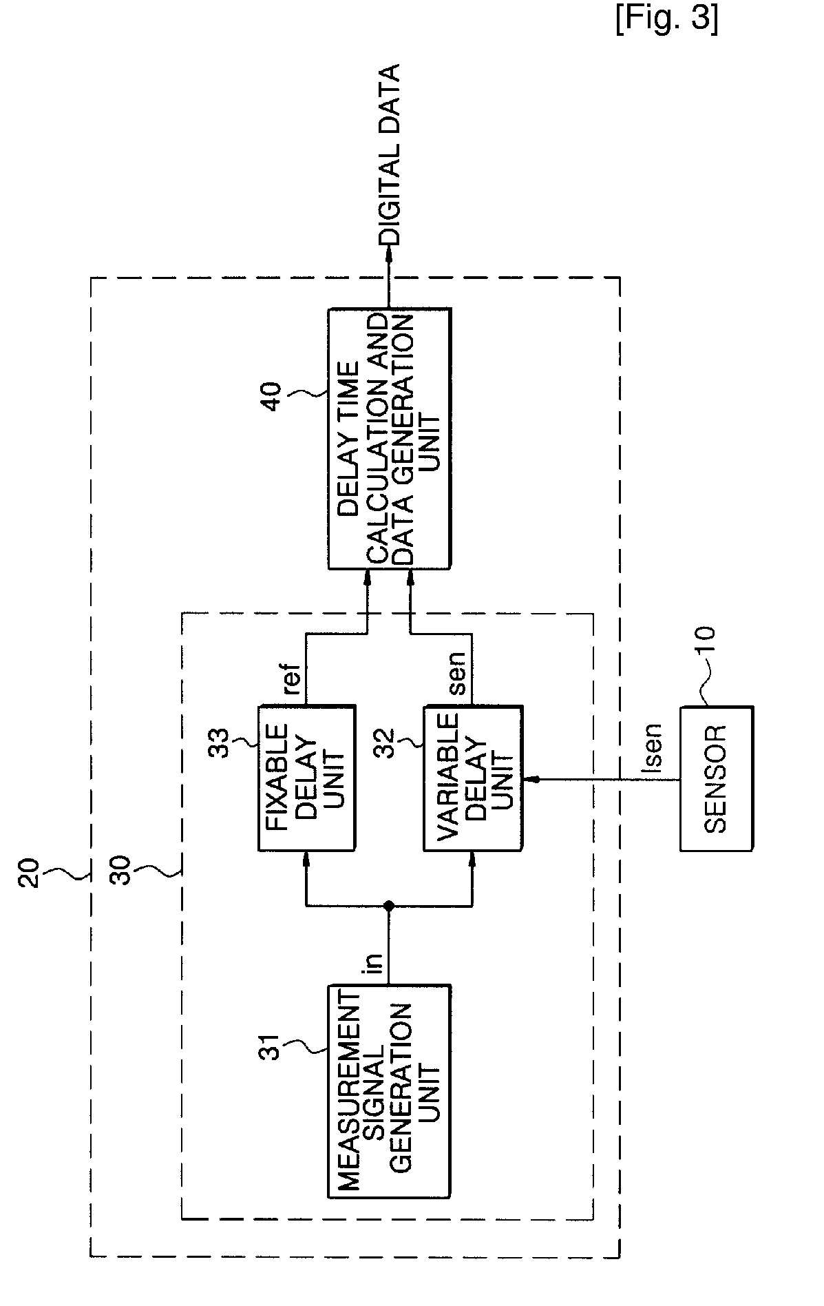
[0050]FIG. 3 illustrates the configuration of a time-to-digital converting circuit in accordance with the present invention.

[0051]Referring to FIG. 3, the time-to-digital converting circuit includes a delay time-varying unit 30, and a delay time calculation and data generation unit 40, and the delay time-varying unit 30 has a measurement signal generation unit 31, a variable delay unit 32, and a fixable delay unit 33.

[0052]In this case, a sensor 10 varies an impedance Isen in accordance with external stimulus strength. Accordingly, any kind of elements allowing an electrostatic capacitance, an inductance, or a resistance to be varied depending on the external stimulus strength may be employed as the sensor 10.

[0053]Hereinafter, functions of respective constitutional components will be described.

[0054]The delay time-varying unit 30 generates a sensing signal sen and a reference signal ref, which have a delay time difference therebetween in proportion to an impedance Isen of the senso...

second embodiment

[0093]FIG. 10 illustrates a detailed circuit according to the delay time calculation and data generation unit of FIG. 3.

[0094]Referring to FIG. 10, a delay time calculation and data generation unit 40b has a read signal generation unit 45, a reset signal generation unit 46, a delay signal generation unit 47, a thermometer code generation unit 48, and a binary code decoder 49.

[0095]The read signal generation unit 45 is composed of an inverter I1 inverting and delaying the reference signal ref, inverters I2 and I3 delaying the sensing signal sen, and an AND gate AND1 performing an AND operation on the inverted and delayed reference signal ref and the delayed sensing signal sen to generate a read signal read to be clocked in synchronization with a rising edge of the inverted and delayed reference signal ref, and the reset signal generation unit 46 is composed of inverters I4 and I5 delaying the sensing signal sen, an XOR gate XOR performing an XOR operation on the delayed sensing signa...


PUM


Abstract

A time-to-digital converting circuit and a pressure sensing device using the same are provided. The circuit includes: a delay time-varying unit generating a reference signal having a fixed delay time, and a sensing signal having a variable delay time in response to an impedance of an externally applied signal; and a delay time calculation and data generation unit calculating a delay time difference between the reference signal and the sensing signal, and generating digital data having a value corresponding to the calculated delay time difference. Accordingly, the digital data are generated using the delay time varied in response to the externally applied signal, so that the size of the time-to-digital circuit is significantly reduced. In addition, an affect due to external noises is minimized.

Description

TECHNICAL FIELD[0001]The present invention relates to a time-to-digital converting circuit and pressure sensing device using the same, and more particularly, to a time-to-digital converting circuit and pressure sensing device using the same which varies a delay time difference between a reference signal and a sensing signal depending on external stimulus strength, and calculates the varied delay time difference to generate digital data having a value corresponding to the external stimulus strength.BACKGROUND ART[0002]Recently, a voltage-to-digital converting circuit is widely employed as a signal converting circuit, which receives an external voltage of which the magnitude varies to convert the voltage having the magnitude to digital data.[0003]FIG. 1 illustrates the configuration of a conventional voltage-to-digital converting circuit. Referring to FIG. 1, the conventional voltage-to-digital converting circuit 2 includes a voltage generation unit 3, a signal amplification unit 4, a...

Claims


Application Information

Patent Timeline
IPC IPC(8): G01L9/00H03M1/12
CPCG04F10/005G04F10/06
Inventor SHIN, YOUNG-HOLEE, SANG-JINLEE, BANG-WON
Owner ATLAB INC
Why Eureka
Try Eureka