
Low power CMOS voltage reference circuits

a low-power, reference circuit technology, applied in pulse generators, instruments, pulse techniques, etc., can solve the problems of voltage reference block in analog circuits, block voltage reference in analog circuits, and the supply voltage is reduced

Inactive Publication Date: 2008-12-04
IBM CORP
View PDF6 Cites 20 Cited by
  • Summary
  • Abstract
  • Description
  • Claims
  • Application Information

AI Technical Summary

Problems solved by technology

As a result, integrated circuits that consist of both analog and digital circuits are required to be operated at a supply voltage lower than 1.5 V. Furthermore, advances in CMOS processes also demand the reduction in supply voltage down to the same level due to reliability issues for sub-micron CMOS processes.
However, this trend presents a great challenge in designing analog circuits such as amplifiers, filters, and data converters, due to the fact that the threshold voltages of the devices in these processes do not scale down at the same rate as the supply voltages.
Another important building block in analog circuits is the voltage reference, which is usually required in many analog and mixed signal systems such as communication systems and data acquisition systems, as well as some digital systems such as dynamic random access memories (DRAM's).
However, the conventional CMOS bandgap reference does not work for lower power supply voltages (like 1 Volt) as the minimum output voltage of the conventional Bandgap reference is 1.23 V, which is limited by the bandgap of silicon.
However, the supply voltages of most bandgap references are, in fact, limited by the input common mode range of the operational amplifier (opamp), which is required to produce a proportional to the absolute temperature (PTAT) voltage or current.
Without a way to provide a stable reference voltage particularly for low temperature variations the promise of this technology may never be fully achieved.

Method used


Image

  • Low power CMOS voltage reference circuits
  • Low power CMOS voltage reference circuits
  • Low power CMOS voltage reference circuits

Examples


Embodiment Construction

[0014]Where reference is made in any one or more of the accompanying drawings to steps and / or features, which have the same reference numerals, those steps and / or features have for the purposes of this description the same function(s) or operation(s), unless the contrary intention appears. The terms VDD refers to a positive voltage supply to the circuit and the term VSS refers to negative voltage supply or the ground. The term reference current, current proportional to absolute temperature, (IPTAT) current are used synonymously.

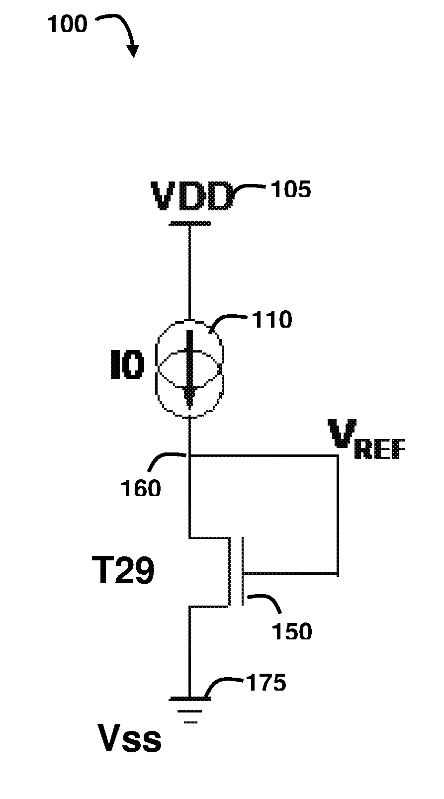
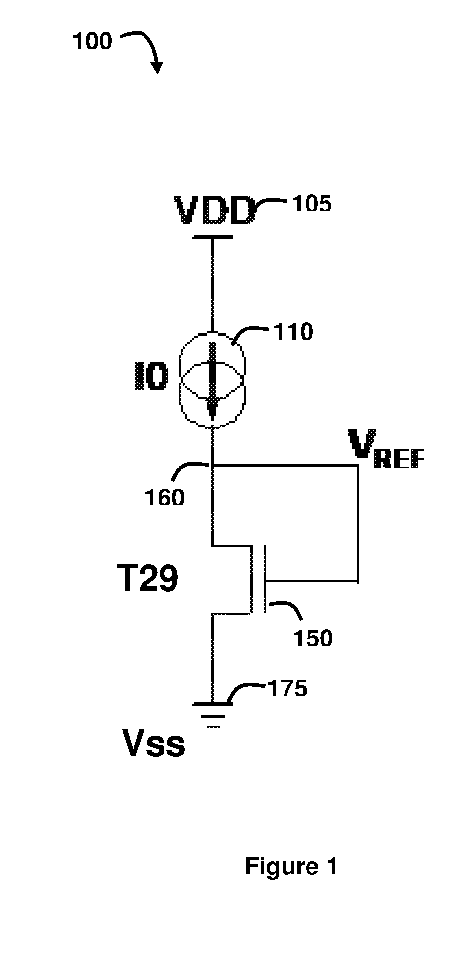
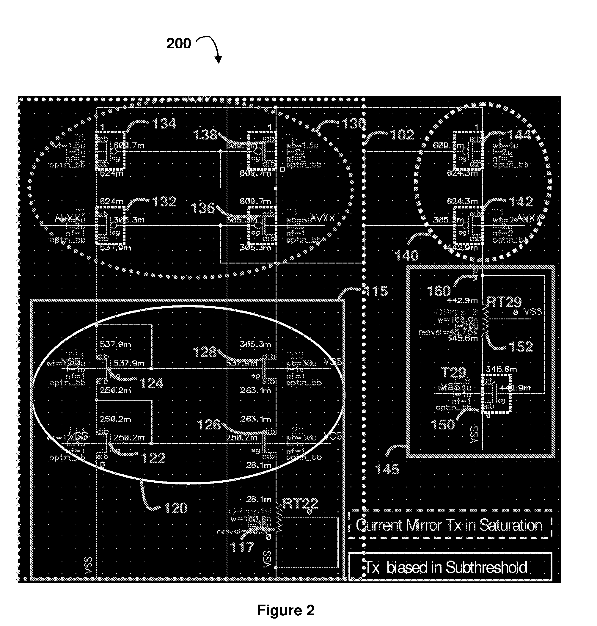
[0015]FIG. 1 illustrates an exemplary embodiment of a circuit 100 configured to provide a stable reference voltage (VREF). The circuit 100 is coupled between a positive voltage supply 105 (VDD), which supplies a respective voltage to the circuit 100, and a negative voltage supply 175 (VSS), which is also referred to as the ground connection. The circuit 100 consists of a current source circuit 110, which is configured to generate and provide a current that is...


PUM


Abstract

A CMOS voltage reference circuit for a low voltage (1v), low power supply application is described. The circuit achieves a temperature coefficient of 31 ppm for a relatively large temperature range of −40 C to 125 C. A combination of subthreshold current characteristics and moderate inversion operation of MOSFET's are utilized in conjunction to achieve a fairly stable temperature independent output voltage reference (VREF) from the circuit.

Description

FIELD OF THE INVENTION[0001]This invention relates to a temperature compensated low power voltage reference circuit, for providing relatively stable voltage reference over a relatively large temperature range.BACKGROUND OF THE INVENTION[0002]Designing analog circuits at low supply voltage has become increasingly important. This is due to the fact that there is a great demand in battery-powered portable devices and systems. As a result, integrated circuits that consist of both analog and digital circuits are required to be operated at a supply voltage lower than 1.5 V. Furthermore, advances in CMOS processes also demand the reduction in supply voltage down to the same level due to reliability issues for sub-micron CMOS processes. However, this trend presents a great challenge in designing analog circuits such as amplifiers, filters, and data converters, due to the fact that the threshold voltages of the devices in these processes do not scale down at the same rate as the supply volta...

Claims


Application Information

Patent Timeline
Patent Type & Authority Applications(United States)
IPC IPC(8): G05F1/567G05F1/10
CPCG05F1/567
Inventor RAMAMOORTHY, NAVIN KUMAR
Owner IBM CORP
Learn More