Magnification Observation Apparatus and Method For Photographing Magnified Image

a technology of magnified image and observation apparatus, which is applied in the field of magnification observation apparatus, can solve the problems of not having a magnification observation apparatus capable of switching, halation, and limited dynamic range of image imaged with the ccd, and achieves enhanced luminance resolution, enhanced luminance resolution, and enhanced tone

Active Publication Date: 2008-12-04
KEYENCE
View PDF4 Cites 51 Cited by
  • Summary
  • Abstract
  • Description
  • Claims
  • Application Information

AI Technical Summary

Benefits of technology

[0010]In order to achieve the above object, a magnification observation apparatus according to the present invention relates to a magnification observation apparatus capable of displaying an image obtained by imaging a sample to be imaged according to a set imaging condition, the magnification observation apparatus including an imaging condition setting part that sets at least an exposure time as the imaging condition when imaging an original image in an imaging unit; the imaging unit that images the original image having a predetermined dynamic range, which is a ratio between minimum luminance and maximum luminance, according to the imaging condition set in the imaging condition setting part with respect to an observation position of the sample; a synthesized image generating part that generates synthesized image data that is higher in tone than a tone width of the original image by synthesizing a plurality of original images imaged under different imaging conditions at the same observation position of the sample; a display unit that displays an image imaged by the imaging unit; and a mode selecting part that selects, as a synthesized image photography mode for acquiring the synthesized image from the plurality of original images imaged in the imaging unit, either a dynamic range widening photography mode for generating the synthesized image having a dynamic range wider than that of the original image, and a resolution enhancing photography mode for enhancing a luminance resolution from the original image in a dynamic range narrower than that of the original image. According to such a configuration, a synthesized image in which the luminance resolution is enhanced within a narrow dynamic range can be acquired in addition to the dynamic range widening photography mode when generating the synthesized image, whereby the textures can be easily distinguished even with respect to a sample that barely has contrasting density such as ceramic.

Problems solved by technology

Thus, the range that can be represented (dynamic range) of the image imaged with the CCD is limited compared to the human eye.
In this case, if the tone of the image to be imaged exceeds such a range, saturation occurs, thereby causing underexposure, overexposure, halation, and the like.
Also, there has not been a magnification observation apparatus capable of switching between the dynamic range widening application and the luminance resolution enhancing application, and automatically determining in which application a user desires to photograph.

Method used


Image

  • Magnification Observation Apparatus and Method For Photographing Magnified Image
  • Magnification Observation Apparatus and Method For Photographing Magnified Image
  • Magnification Observation Apparatus and Method For Photographing Magnified Image

Examples


first embodiment

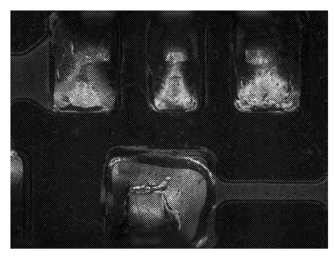
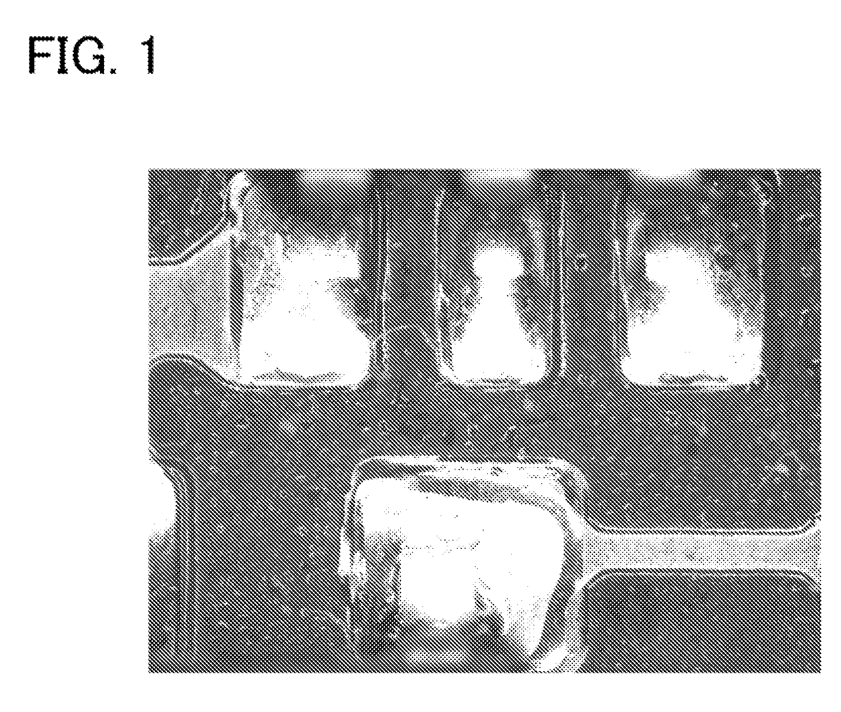
[0042]A magnification observation apparatus according to a first embodiment of the present invention will be described with reference to FIGS. 4 and 5. As shown in FIG. 4, the magnification observation apparatus includes an illumination unit 60 for illuminating a sample (subject) to be observed, an imaging unit 10 that images the sample illuminated by the illumination unit 60, and an information processing apparatus 50 including a display unit 52 that displays a magnified image imaged with the imaging unit 10. The magnification observation apparatus of FIG. 4 also includes a sample fixing unit (stage 30 to be mounted with a sample S) that fixes the sample, an imaging device (CCD 12) that electrically reads reflected light or transmitted light from the sample S fixed to the sample fixing unit entering through an optical system 11, and a focus adjusting unit (stage lifting / lowering unit 20) that adjusts a focus by changing the relative distance in an optical axis direction of the samp...

second embodiment

[0054]A laser microscope will now be described with reference to FIG. 6 as a magnification observation apparatus according to a second embodiment of the present invention. In the magnification observation apparatus of the second embodiment, the camera serving as the imaging unit includes a first imaging unit in which the reflected light of the light from a first light source (laser 101) emitted on the sample S is received by a first light receiving device (photodiode 112) through a first optical system 100, and a second imaging unit in which the reflected light of the light from a second light source (white lamp 201) emitted on the sample S is received by a second light receiving device (CCD 212) through a second optical system 200.

[0055]The first imaging unit will be described first. The first optical system 100 includes a laser 101 that emits monochromatic light (e.g., laser beam) to the sample S, a first collimator lens 102, a polarization beam splitter 103, a ¼ wavelength plate ...


PUM


Abstract

A high tone image is saved in a versatile image file format to enhance usability. There are provided an imaging unit that images an original image having a predetermined dynamic range, which is a ratio between minimum luminance and maximum luminance; a synthesized image generating part that generates a synthesized image data that is higher in tone than a tone width of the original image by synthesizing a plurality of original images imaged under different imaging conditions at the same observation position; a display unit that displays the images imaged by the imaging unit; a tone conversion part that converts the synthesized image data generated by the synthesized image generating part to low tone image data having a tone width capable of being displayed on the display unit; and a tone data saving part that generates a high tone data-attached display file including a high tone image region for saving the synthesized image data serving as a basis as an image file for saving the low tone image data.

Description

BACKGROUND OF THE INVENTION[0001]1. Field of the Invention[0002]The present invention relates to a magnification observation apparatus such as a digital microscope and a microscope that images and displays a magnified image, and a method for photographing a magnified image.[0003]2. Description of the Related Art[0004]A magnification observation apparatus that magnifies and displays a subject such as a sample including a minuscule object and a workpiece utilizes an optical microscope and digital microscope using an optical lens, and the like. The digital microscope receives reflected light or transmitted light from an observation target fixed at an observation target fixing unit entering through an optical system with a light receiving device such as a CCD, which electrically reads the light for every pixel arranged two-dimensionally, and displays the electrically read image on a display unit such as a display (e.g., see Japanese Laid-Open Patent Publication No. 2002-135648).[0005]Th...

Claims


Application Information

Patent Timeline
Patent Type & Authority Applications(United States)
IPC IPC(8): H04N7/18H04N5/235G02B21/36G03B7/08G03B7/093G03B15/00G03B19/02H04N5/225
CPCG02B25/002G03B7/00H04N1/407H04N5/23245H04N5/2353H04N5/2354H04N5/2355H04N5/349H04N23/667H04N23/741H04N23/73H04N25/48H04N23/74G02B21/0004
Inventor INOMATA, MASAHIROWOOBUM, KANG
Owner KEYENCE
Why Eureka
Try Eureka