[0009]The present invention has been made taking the foregoing circumstances into consideration, an object of which is to provide an
exposure technique and a device-producing technique wherein high
overlay accuracy is obtained even when the alignment information including, for example, the linear expansion and contraction of a substrate is gradually changed during the exposure of the substrate such as a wafer.
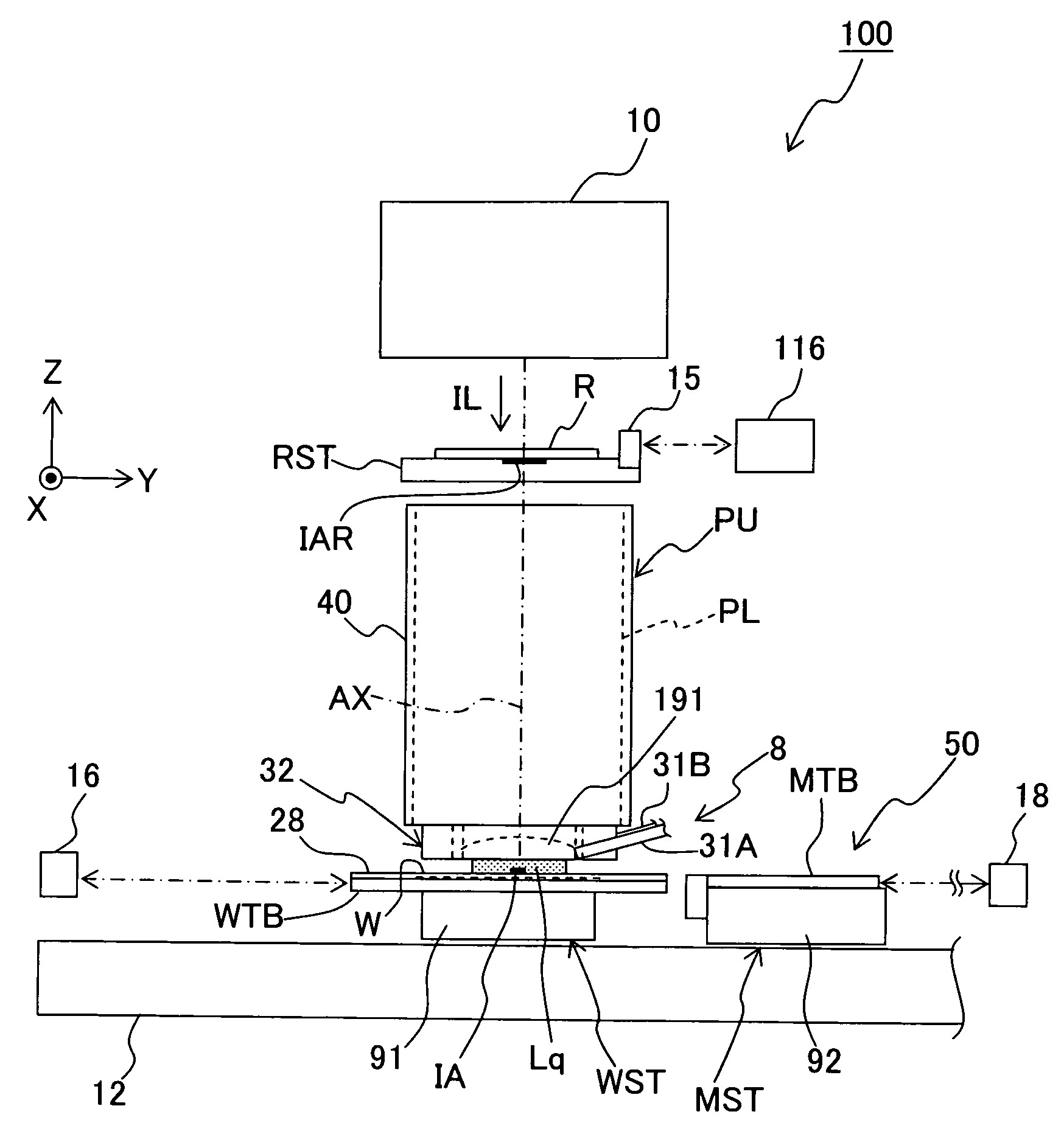
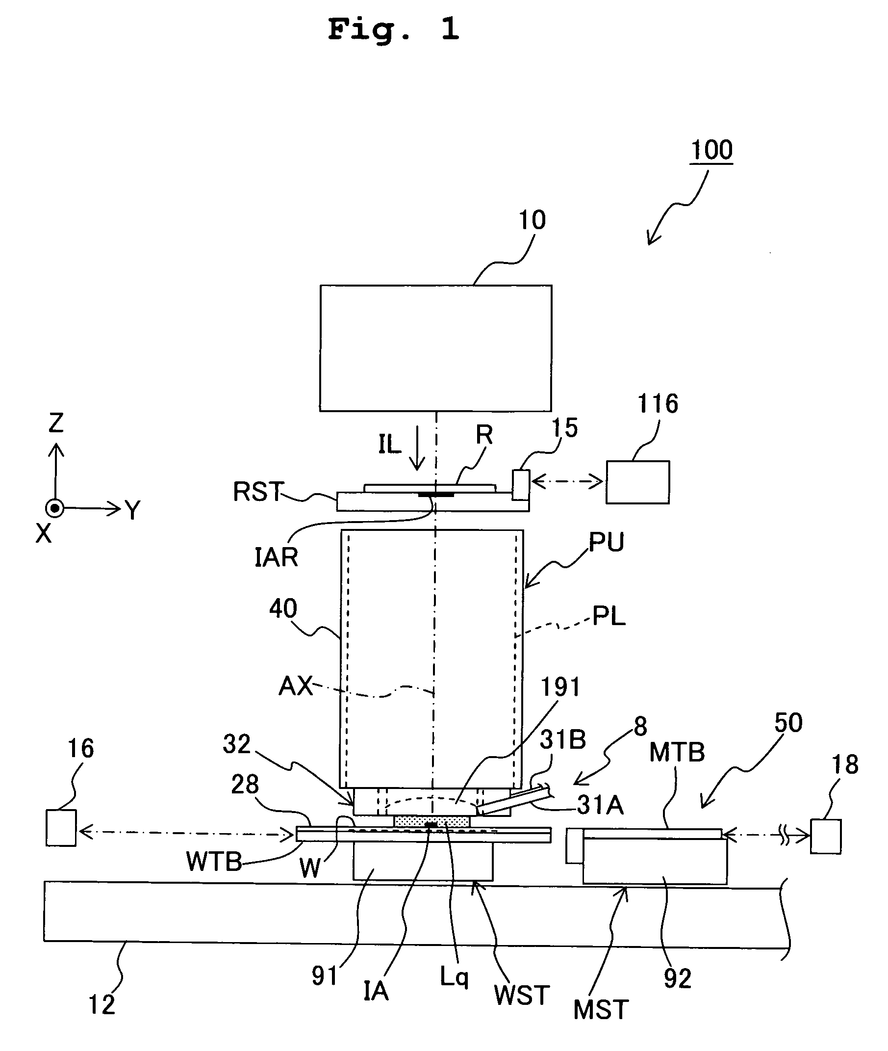
[0010]According to a first aspect of the present invention, there is provided an exposure method for exposing a substrate via a pattern with an exposure light by illuminating the pattern with the exposure light, the exposure method comprising: performing measurement of alignment information of a first substrate before and after exposure of the first substrate; and correcting alignment information of a second substrate before exposure of the second substrate, based on a result of the measurement. According to this invention, the fluctuation or variation of the alignment information during the exposure is determined from the alignment information obtained both before and after the exposure in relation to the first substrate. Therefore, the alignment information of the second substrate is corrected based on the fluctuation, thereby improving the overlay accuracy of the second substrate.
[0011]According to a second aspect of the present invention, there is provided an exposure method for exposing a substrate via a pattern with an exposure light by illuminating the pattern with the exposure light, the exposure method comprising: a first step of performing measurement of alignment information of a first substrate before exposure of the first substrate; a second step of exposing the first substrate via the pattern while performing alignment for the first substrate based on a result of the measurement in the first step; a third step of performing measurement of alignment information of the first substrate after the exposure of the first substrate; and a fourth step of determining a fluctuation amount of the alignment information measured in the third step with respect to the alignment information measured in the first step. According to the present invention, the alignment information of a substrate to be exposed next is corrected by using the fluctuation amount of the alignment information determined in the fourth step. Thus, the overlay accuracy of the next substrate is improved.
[0012]According to a third aspect of the present invention, there is provided an exposure method for exposing a substrate with an exposure light, the exposure method comprising: performing exposure of a first substrate with the exposure light, and then performing detection of a mark disposed on the first substrate after the exposure; and performing exposure of a second substrate by using a result of the detection of the mark. According to the present invention, for example, the result of the detection of the mark of the second substrate (alignment information) is corrected based on the result of the detection of the mark of the first substrate, thereby improving the overlay accuracy of the second substrate.
[0013]According to a fourth aspect of the present invention, there is provided an exposure method for exposing a substrate with an exposure light, the exposure method comprising: performing detection of a mark of a first substrate both before and after exposure of the first substrate with the exposure light; and determining alignment information of a second substrate by using a result of the detection after the exposure. According to the present invention, for example, the result of the detection of the mark of the second substrate is corrected based on the result of the detection of the mark of the first substrate to determine the alignment information of the second substrate, thereby improving the overlay accuracy of the second substrate.
[0017]Further, a method for producing a device according to the present invention comprises: exposing a substrate by using the exposure method of the present invention; developing the exposed substrate; and
processing the developed substrate. Since this method for producing the device uses the exposure method of the present invention, the device can be produced highly accurately.

