Liquid container with variable extraction chimney

a liquid container and variable technology, applied in the field of liquid containers, can solve the problems of no ventilation path of sufficient magnitude for pressure equalization, liquid slosh in the container and possibly spraying upwards, and no liquid permeability. , to achieve the effect of greater liquid permeability and high throughpu

Active Publication Date: 2008-12-04
ROCHE DIAGNOSTICS OPERATIONS INC
View PDF4 Cites 2 Cited by
  • Summary
  • Abstract
  • Description
  • Claims
  • Application Information

AI Technical Summary

Benefits of technology

[0013]According to the present invention, a liquid container filled with liquid for use in high throughput automatic analyzers can comprise a top opening, an extraction chimney and a base. The extraction chimney can extend into the liquid container and can be aligned with the top opening of the liquid container. The extraction chimney can comprise a liquid-permeable zone that can be proximate to a bottom region of the extraction chimney and can be adjacent to the base of the liquid container. The liquid permeability of the liquid-permeable zone of the extraction chimney can be adjusted between a setting of minimal liquid permeability and a setting for greater liquid permeability. The extraction chimney can remain in the liquid container during the adjustment of the liquid permeability. The liquid can then be withdrawn from the liquid container by a liquid extraction element, such as, for example, a pipette, introduced into the extraction chimney through the top opening when the liquid permeability is set at the setting of minimal liquid permeability.

Problems solved by technology

This short cycle time gives rise to the problem where, when the liquid container is stopped abruptly in the pipetting zone, the liquid sloshes in the container and possibly sprays upwards.
This remaining liquid then may give rise to contamination in further pipetting operations.
In this case, there is no ventilation path of sufficient magnitude for pressure equalization between the liquid container interior and the surroundings between the outside of the extraction chimney and the inner surface of the opening nozzle.
However, this restriction of the liquid permeability, which is necessary for the desired functioning of the extraction chimney, is also associated with a disadvantage.
Therefore, filling the liquid container too quickly may result in the liquid overflowing at the top opening of the liquid container.
Even conventional liquid containers in which the extraction chimneys are to be inserted after the liquid has been introduced into the liquid containers may have the problem of overflow of liquid through the top container openings.

Method used


Image

  • Liquid container with variable extraction chimney
  • Liquid container with variable extraction chimney
  • Liquid container with variable extraction chimney

Examples


Embodiment Construction

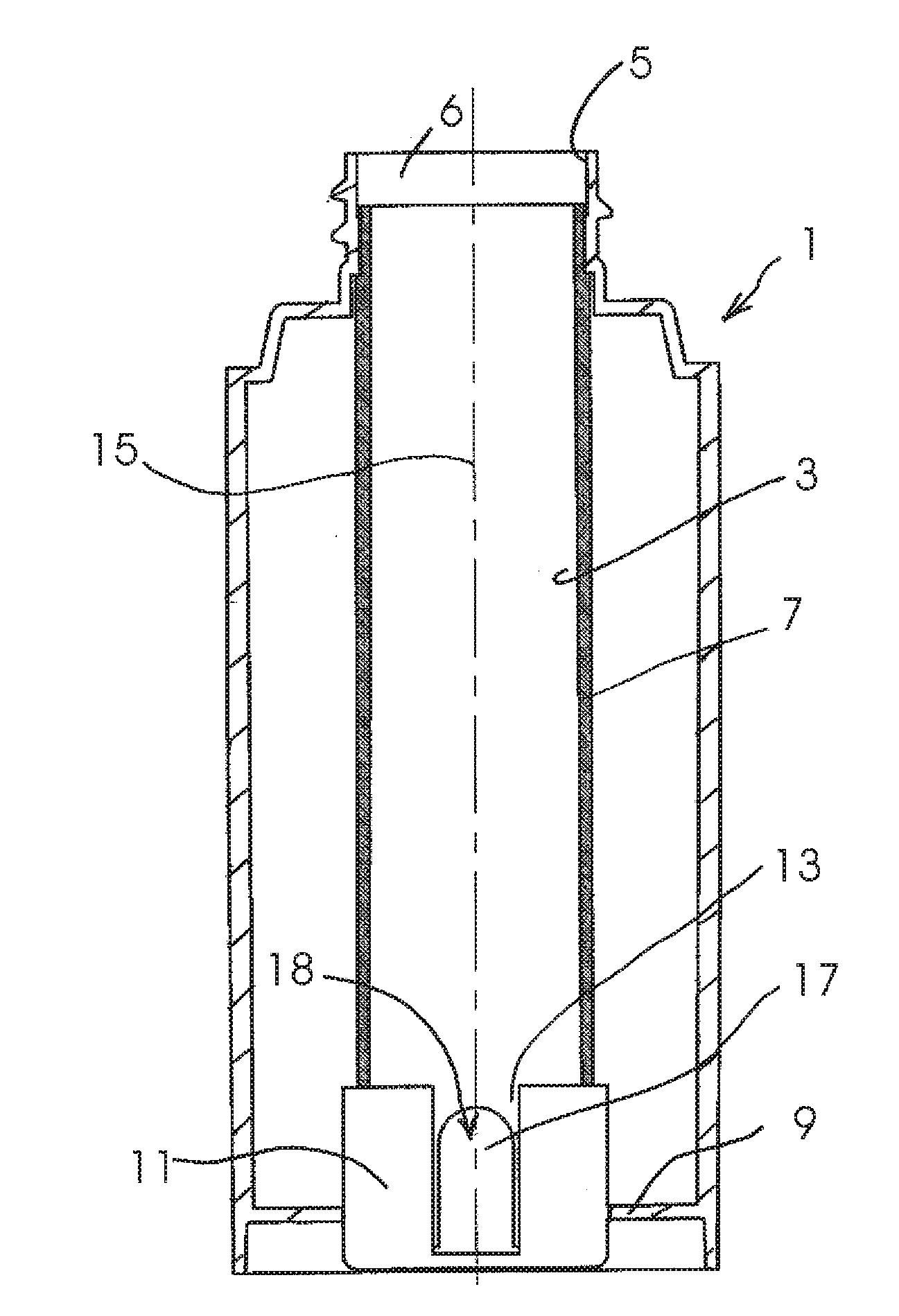
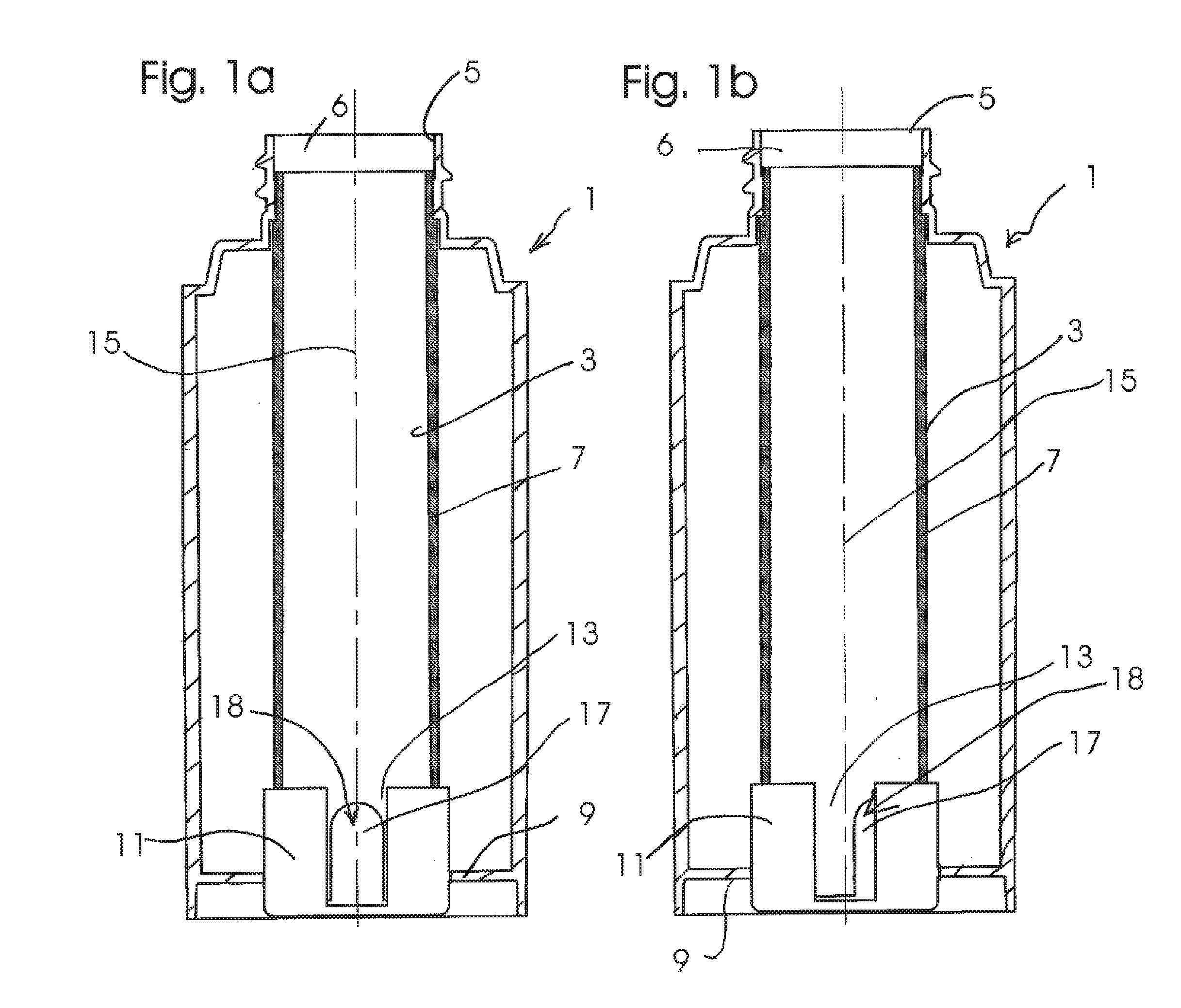
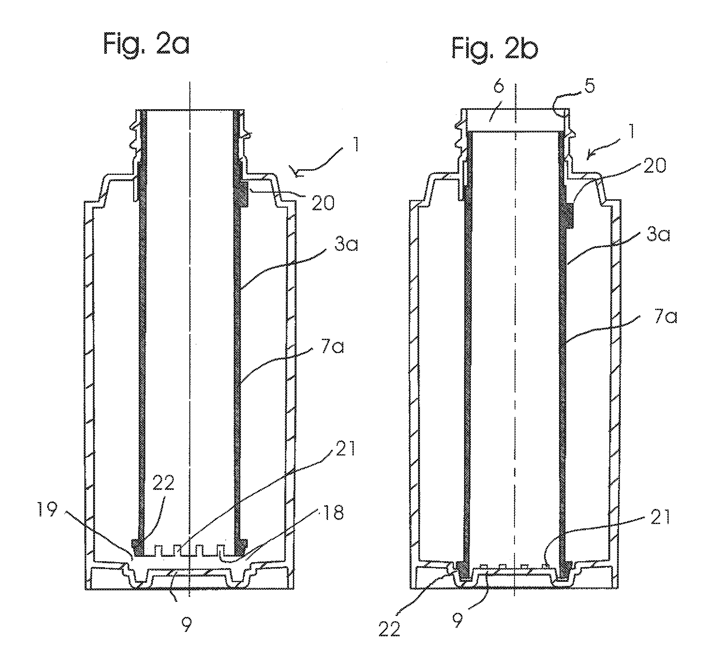
[0020]In the following detailed description of the embodiments, reference is made to the accompanying drawings that form a part hereof, and in which are shown by way of illustration, and not by way of limitation, specific embodiments in which the invention may be practiced. It is to be understood that other embodiments may be utilized and that logical, mechanical and electrical changes may be made without departing from the spirit and scope of the present invention.

[0021]A particularly advantageous use of the liquid container according to the present invention can be the way the liquid can be introduced into the liquid container at a high-speed automatic filling station. During high throughput operation to prepare the liquid container for subsequently providing the liquid in a high-speed automatic analyzer, the extraction of liquid in the automatic analyzer taking place by virtue of liquid being extracted from the liquid container by suction using a pipette or the like, with the ext...


PUM


Abstract

A liquid container having a top opening, a base, and an extraction chimney which extends into the container and which is in alignment with the top opening is presented. The extraction chimney is intended for the withdrawal of liquid by a liquid-withdrawal element that is introduced into the liquid container through the extraction chimney. The extraction chimney has a liquid-permeable zone in its bottom region, adjacent to the liquid container base. The liquid permeability of the liquid-permeable zone of the extraction chimney can be adjusted between a setting for minimal liquid permeability and a setting for greater liquid permeability. The extraction chimney can be adjusted while the extraction chimney remains in the liquid container.

Description

CROSS-REFERENCE TO RELATED APPLICATIONS[0001]This application claims priority benefit to European Patent Application Number EP 07 010 826.1, filed May 31, 2007.FIELD OF THE INVENTION[0002]The present invention relates to liquid containers used in high throughput automatic analyzers, and in particular, to a liquid container used as a reagent liquid vessel in automatic analyzers having a top opening and having a tube-like extraction chimney which extends into the liquid container and is in alignment with the top opening and is intended for the extraction of liquid by an extraction element, such as, for example, a pipette, which can be introduced into the extraction chimney through the top opening.BACKGROUND OF THE INVENTION[0003]Liquid containers which are used as reagent liquid vessels in automatic analyzers can have reagent liquid extracted from them by automatic pipetting. In general, the pipetting takes place, in more modern systems, at high speeds in order to allow a high through...

Claims


Application Information

Patent Timeline
Patent Type & Authority Applications(United States)
IPC IPC(8): B01L3/00B01L99/00
CPCB01L3/08B01L2200/026B01L2200/16B01L2300/046Y10T436/25B01L2400/0644B01L2400/065B65D81/3222B01L2300/049B01L3/523
Inventor SENFTNER, GOTTFRIEDWINKENBACH, MARKUS
Owner ROCHE DIAGNOSTICS OPERATIONS INC
Why Eureka
Try Eureka