

Stopper and plunger rod for a pre-filled syringe
- Summary
- Abstract
- Description
- Claims
- Application Information
AI Technical Summary
Benefits of technology
Problems solved by technology
Method used
Image

Examples
first embodiment
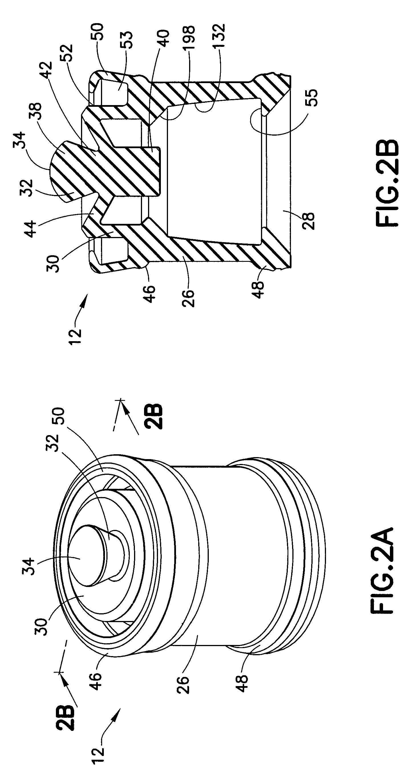
[0072]A feature of the stopper design of the first embodiment illustrated in FIGS. 2A, 2B and 3 is a forward extending skirt 50 extending from the closed front end 30 of the main body 26. Due to the elasticity and / or flexibility of the forward extending skirt 50, the forward extending skirt 50 is capable of deforming by deflecting radially inwardly toward and substantially in contact with an outer portion 52 of the main body 26. Such deflection may occur upon insertion of the stopper 12 within the syringe barrel 16 to form an air pocket 53 to trap an air bubble therein. The air bubble trapped within air pocket 53 assists in the anti-reflux capabilities of the present invention as discussed in detail below. Upon insertion of the stopper 12 into the syringe barrel 16, the forward extending skirt 50 may be adapted to create a positive pressure within the syringe barrel 16.
[0073]In one embodiment, the main body 26 includes at least one undercut portion 55 extending axially inward from t...
third embodiment
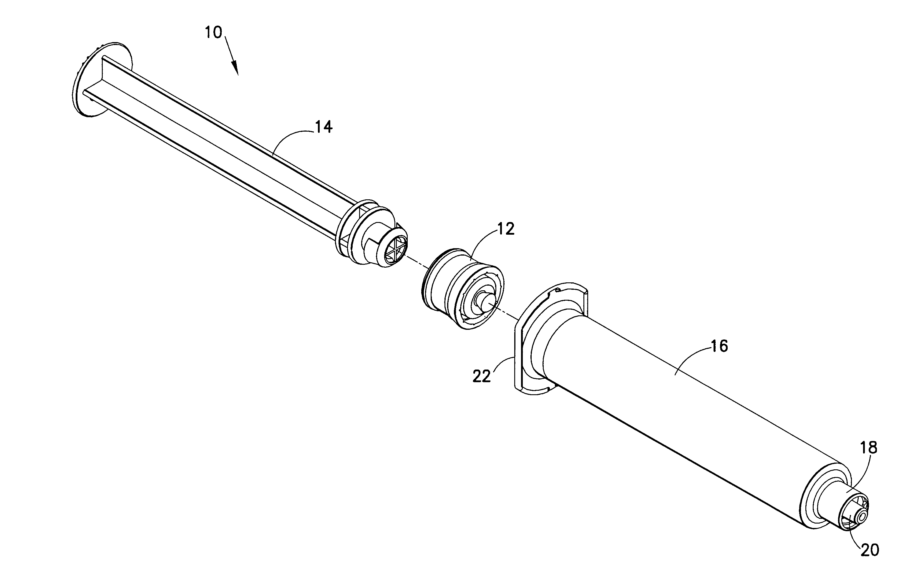
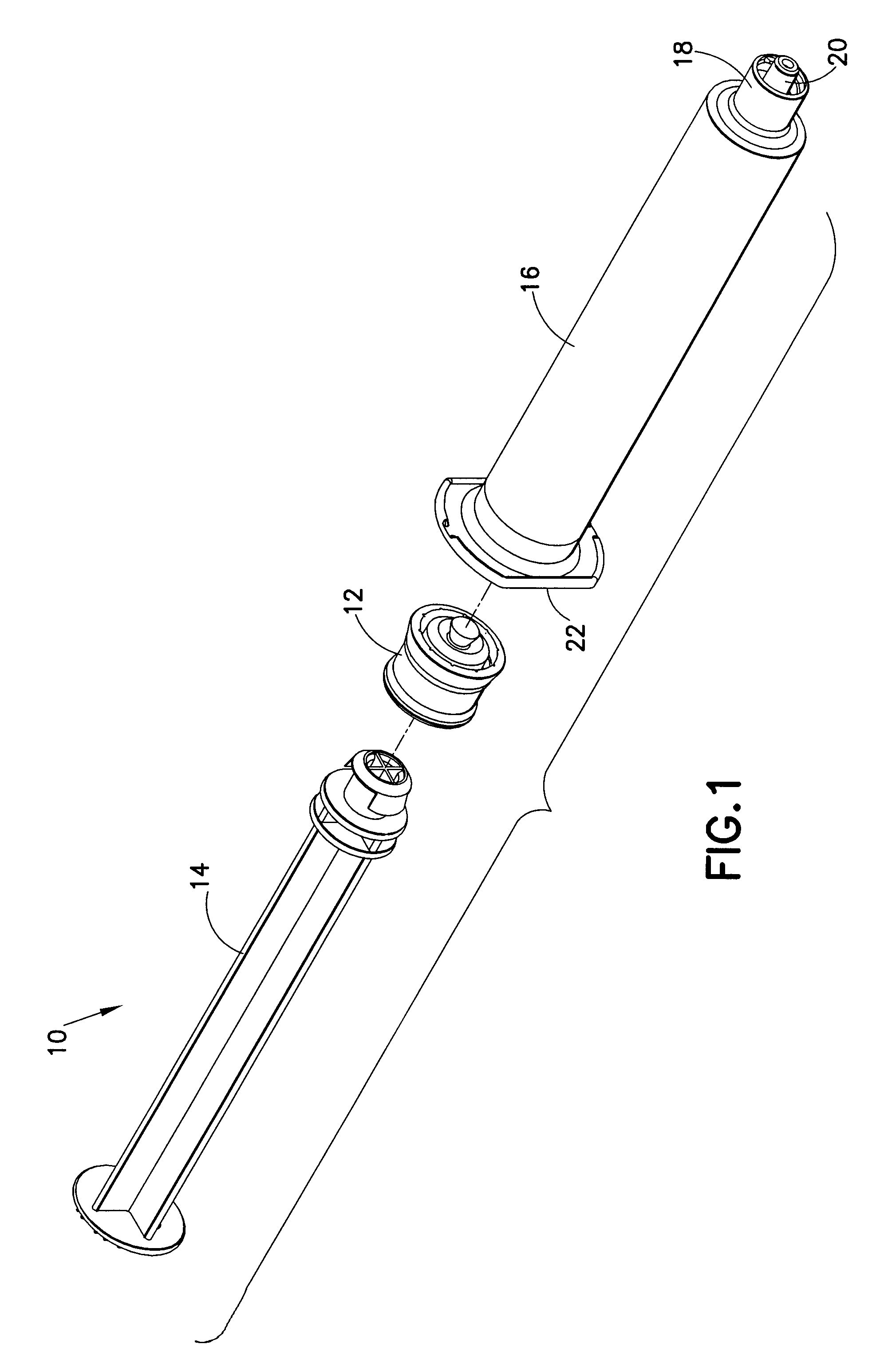
[0077]According to the invention, as illustrated in FIGS. 5A and 5B, an active seal achieves the same result as that of the previously discussed embodiments, but with a different mechanism, commonly referred to as a “Lip Seal” when used in hydraulic applications. The stopper, generally indicated as 254, includes this lip seal. The front seal 256 of the stopper 254 is located on the leading edge of a flexible arm 258. Initial sealing pressure is generated by the interference of the flexible arm 258 with the wall of the syringe barrel 16, as shown in FIG. 1. When the pressure in the syringe barrel 16 increases, this pressure applies an outward radial force to the inside 259 of the flexible arm 258. This outward force will increase the force with which the seal 256 presses against the inside wall of the syringe barrel 16.
fourth embodiment
[0078]Reference is now made to FIGS. 6A-6F and 7-9 which show the stopper 12 according to the invention. In this embodiment, the stopper 12 includes a main body 26 having a closed front end 30. The main body 26 can include an open rearward end 28 which is adapted to receive a front forward end attachment portion 31 of the plunger rod 14. As stated above, the front forward end attachment portion 31 is capable of attachment to the stopper 12. The main body 26 includes a first body portion 60 having a first diameter D1, as shown in FIG. 6B, and a second body portion 62 having a second diameter D2, as shown in FIG. 6B, which is larger than the first diameter of the first body portion 60. A shoulder 64 extends around a perimeter of the first body portion 60 of the main body 26. Preferably, this shoulder 64 extends in a radially outward direction with respect to the first body portion 60.
[0079]As stated above with respect to the description of the first embodiment, a flexible core member ...
PUM
 Abstract
Description
Claims
Application Information