Device and Method for Photocoagulation of the Retina

a technology of retinal photocoagulation and retinal coagulation, which is applied in the field of retinal coagulation devices and methods, can solve problems such as inability to create stable solutions

Inactive Publication Date: 2008-12-04
CARL ZEISS MEDITEC AG
View PDF4 Cites 22 Cited by
  • Summary
  • Abstract
  • Description
  • Claims
  • Application Information

AI Technical Summary

Benefits of technology

[0077]The camera is preferably a photo camera. The photo camera preferably takes a picture of the retina at the point in time when the retina is being treated with the beam from the source of radiation. As a result, exactly the information that is of interest to the surgeon is detected in each case. Examples of photo cameras that can be used are digital cameras or analog cameras. The use of a digital camera has the advantage that the images can immediately be further processed by a computer. The use of an analog camera has the advantage that the images can be acquired very accurately on a photo film.

Problems solved by technology

With lower doses, a remnant of the vision could be retained—up until now, it has not been possible to create stable solutions implementing the experiments carried out with such systems that entail feedback with respect to the dose applied in order to control the so-called sub-threshold coagulation.

Method used


Image

  • Device and Method for Photocoagulation of the Retina
  • Device and Method for Photocoagulation of the Retina
  • Device and Method for Photocoagulation of the Retina

Examples


Embodiment Construction

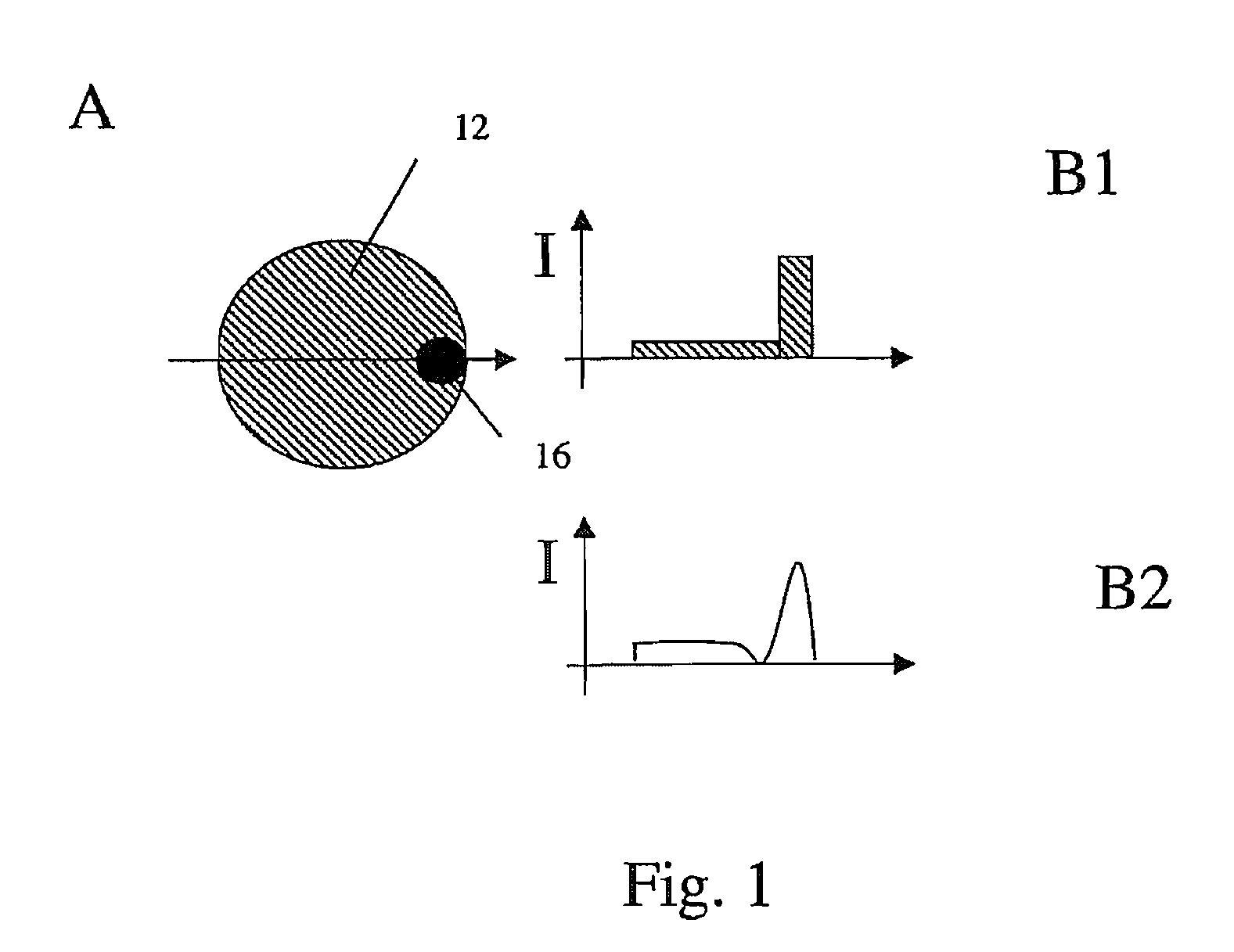
[0090]In FIG. 1, Diagram A shows a projected surface area 12 which encompasses an intensity maximum 16. The homogeneous intensity profile of the laser spot thus exhibits a region of higher intensity 16 that can be visually recognized during the coagulation. Diagram A depicts the intensity distribution in a top view onto the projected surface area 12 of the plane of a retina. The dark maximum 16 indicates a high radiation intensity.

[0091]Diagram B1 depicts the intensity profile along a section through the spot shown in Diagram A along the indicated center line. In this cross section, the intensity is low and constant over a large surface area and increases in the region of the maximum 16. Diagram B1 depicts an ideal intensity distribution as it should be represented on the retina.

[0092]In reality, owing to thermal conduction in the retina, it could be advisable to calculate an intensity distribution that differs from this ideal case, which then results in an intensity distribution on...


PUM


Abstract

A device for photocoagulation of a retina includes a radiation source and an optical application system including a representation device configured to depict regions of the retina with sub-threshold coagulation. In addition a method for photocoagulation of the retina is provided.

Description

[0001]This application is a U.S. National Phase application under 35 U.S.C. § 371 of International Application No. PCT / EP2006 / 008493, filed Aug. 30, 2006, and claims the benefit of German Patent Application No. DE 10 2005 055 885.2, filed Nov. 23, 2005. The International Application was published in German on May 31, 2007 as WO 2007 / 059814 under PCT Article 21 (2).[0002]The invention relates to a device and to a method for photocoagulation of the retina.BACKGROUND[0003]Light coagulation was employed for the first time at the end of the 1940s using the focused light of an axial high-pressure lamp to treat various diseases of the retina, for example, diabetic retinopathy. The retina is heated up and coagulated by the absorption of the laser beam, especially in the pigment epithelium, a dark pigmented layer located in the retina. As a result, the metabolism is focused on the regions of the retina that are still healthy. Moreover, biochemical co-factors are stimulated. As a consequence,...

Claims


Application Information

Patent Timeline
Patent Type & Authority Applications(United States)
IPC IPC(8): A61B18/20
CPCA61B3/12A61F9/00823A61F2009/00863A61F9/008
Inventor WIECHMANN, MARTINDICK, MANFREDZIMARE, DIEGOSCHUETT, REGINA
Owner CARL ZEISS MEDITEC AG
Why Eureka
Try Eureka