Atraumatic Hemostatic Clamp

a technology of a hemostatic clamp and a traumatic field, which is applied in the field of medical instruments, can solve the problems of increasing the mental burden of doctors, the strength of the conventional hemostatic clamp cannot meet actual requirements, and the trauma of the vessel, so as to prevent the slippage of the vessel, improve the safety and convenience of use, and induce adverse influences

Inactive Publication Date: 2008-12-04
XU LIN
View PDF9 Cites 13 Cited by
  • Summary
  • Abstract
  • Description
  • Claims
  • Application Information

AI Technical Summary

Benefits of technology

[0007]Accordingly, in order to optimize the unsatisfactory structure design and solve the problem of the conventional hemostatic clamp that vessel trauma or perforation of vein walls may be easily caused, the present invention is directed to an atraumatic hemostatic clamp capable of providing a reliable grasp without causing trauma to bodily vessels.
[0015]Instead of using the tooth configuration which is proved to have unsatisfactory vessel-occluding effect and even induce adverse influences based on plenty of clinical practices, the present invention adopts a structure with a smooth section having no teeth for gripping the vessel walls. Meanwhile, a groove structure lower than the clamping surface is formed on the clamping surface. Thus, a groove wall formed between the adjacent grooves on one clamping surface can be inserted in the groove on the other clamping surface, so as to ensure the clamping force. In addition, a contact deformation of the vessels gripped by the jaws is generated, and thus the vessels can be firmly gripped by the clamp. Further, the serrated configuration on two ends helps to prevent the slippage of the vessels. Also, the jaws are made thicker, such that this hemostatic clamp is safer and more convenient in use. In addition, the number of the adjustment teeth is increased to achieve a more precise adjustment of the clamping force and a more flexible manipulation.

Problems solved by technology

If the clamping force is too large, the tooth configuration on the jaws might cause perforation to the vessel walls, which leads to vessel trauma.
Therefore, a higher requirement for the control of the clamping force during the operation is raised, which may increase the mental burden of doctors.
The holding feeling and the strength of the conventional hemostatic clamp cannot meet actual requirements and thus need improvements.

Method used


Image

  • Atraumatic Hemostatic Clamp
  • Atraumatic Hemostatic Clamp

Examples


Embodiment Construction

[0021]Hereinafter, the present invention will be illustrated in the following embodiments with the accompanying drawings.

[0022]Refer to FIGS. 1 and 2.

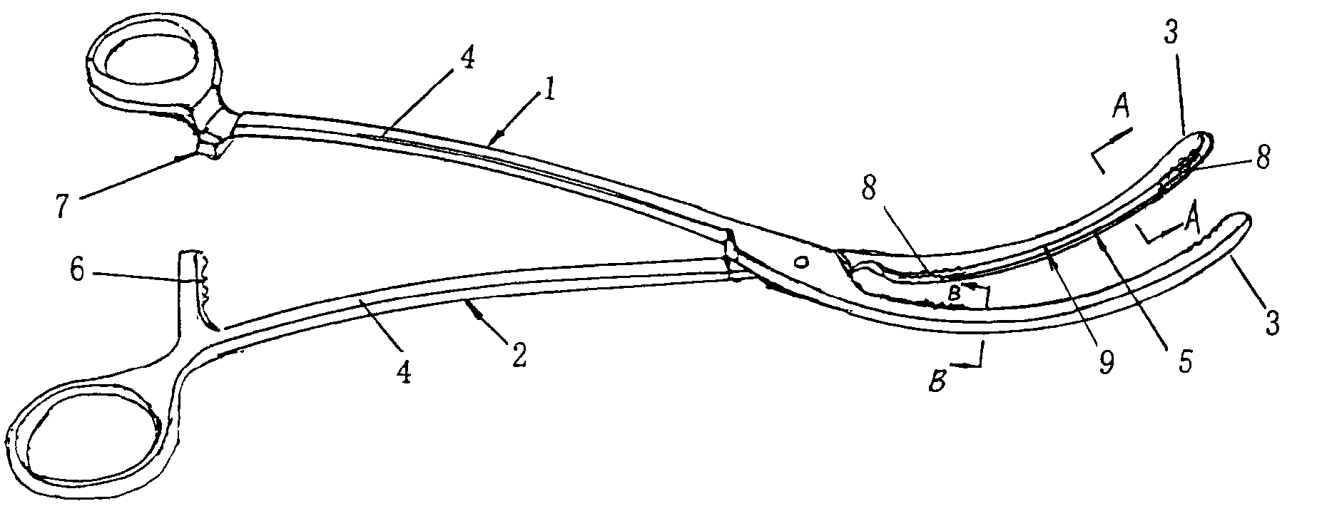
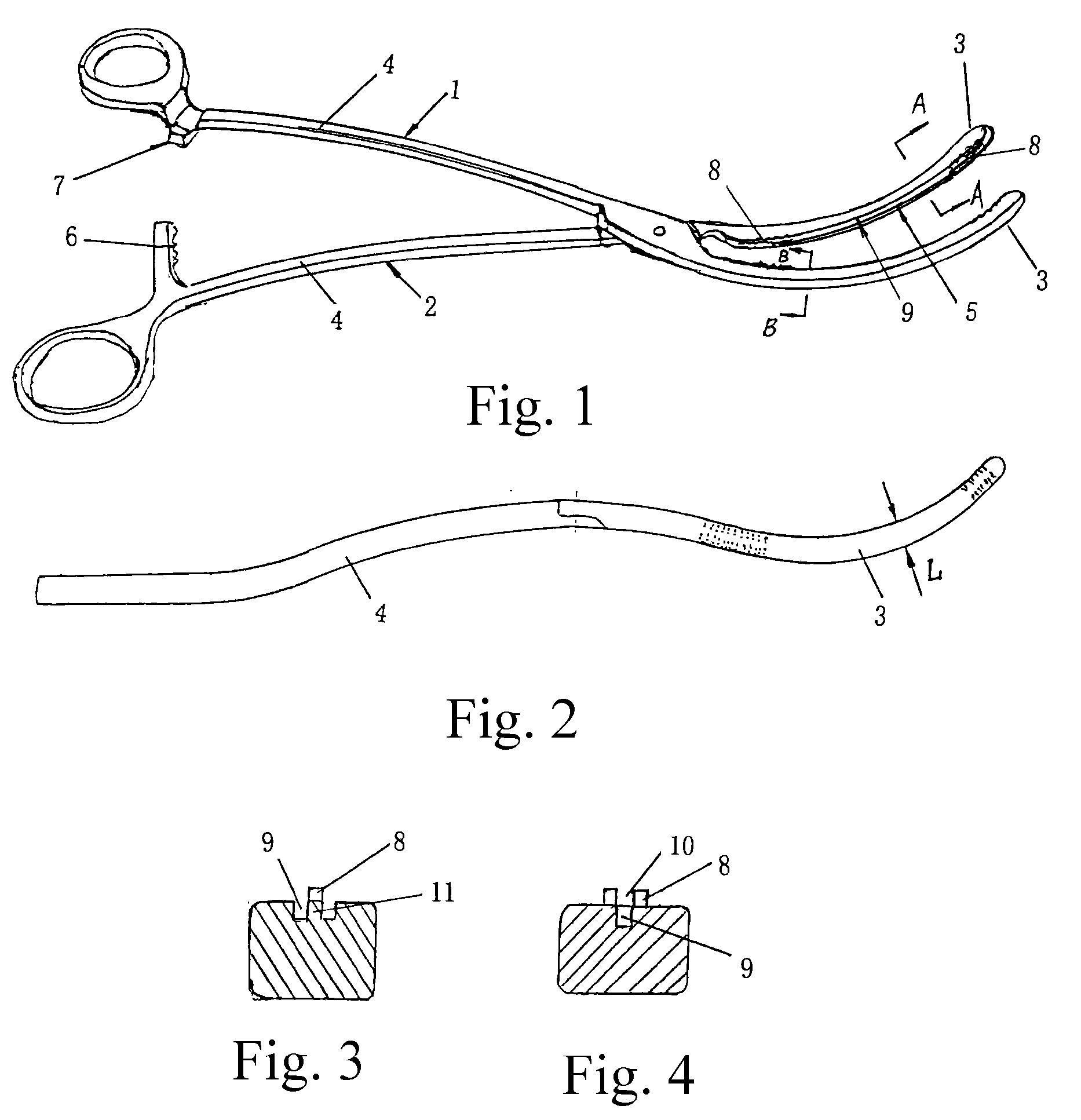
[0023]As shown in FIG. 1, an atraumatic hemostatic clamp made of titanium alloy mainly includes a left clamp body 1 and a right clamp body 2 which are joined by a hinge and may be divided into jaws 3 and handles 4 by the hinge. The jaws 3 of the left and right clamp bodies 1, 2 have a curved configuration with ends extending upwardly. Serrated portion 8 with serrations projecting from the engaging surface are respectively formed on both ends of the jaw 3 of the left clamp body 1 and the jaw 3 of the right clamp body 2. A groove 9 is formed on a non-serrated section 5 between the serrated portions 8 on the two ends. The serrated portions 8 on one jaw 3 have a single row configuration (in FIG. 3). As shown in FIG. 4, the serrated portions 8 on the other jaw3 have a double row configuration, and a slot 10 is formed between the double rows...


PUM


Abstract

An atraumatic hemostatic clamp, being an artery / vein clamp in the field of medical instruments, mainly includes a left clamp body (1) and a right clamp body (2) which are joined by a hinge and may be divided into jaws (3) and handles (4) by the hinge. The jaws (3) have a curved configuration with ends extending upwardly. Serrated portions (8) with serrations projecting from engaging surfaces are formed on both ends of each of the jaws (3) of the left and right clamp bodies (1), (2). A groove (9) is formed between the serrated portions (8) on both ends. Therefore, this atraumatic hemostatic clamp has a simple structure and can provide a reliable grasp without causing trauma to bodily vessels, thus solving the problem of the conventional hemostatic clamp that vessel trauma may be easily caused.

Description

CROSS REFERENCE TO RELATED PATENT APPLICATION[0001]This application claims the priority of the Chinese patent application No. 200720037895.1 filed on May 29, 2007, which is incorporated herein by reference.BACKGROUND OF THE INVENTION[0002]1. Field of the Invention[0003]The present invention relates to a medical instrument, especially a supplementary medical instrument for various surgical operations. In particular, the present invention relates to an atraumatic hemostatic clamp for occluding vein or artery to stop bleeding.[0004]2. Related Art[0005]Currently, in various surgical operations, e.g., pulmonary surgery, the pulmonary vessels must be occluded to prevent the flow of the blood for the convenience of operation. Thus, the pulmonary vascular clamps must be used. However, in order to provide a sufficient clamping force, usually, a tooth configuration is integrally formed on the surfaces of two jaws in contact with the vessels of the conventional pulmonary vascular clamp, so as ...

Claims


Application Information

Patent Timeline
Patent Type & Authority Applications(United States)
IPC IPC(8): A61B17/28
CPCA61B17/282A61B2017/12004A61B2017/2808A61B2017/2837
Inventor XU, LIN
Owner XU LIN
Why Eureka
Try Eureka