Photoelastic Modulator System

a modulator and photoelastic technology, applied in the field of complete optical modulation system, can solve the problems of limiting the application of the device, affecting the purity of the optical modulation, and the design from being widely used, and achieve the effect of high efficiency

Inactive Publication Date: 2008-12-11
ENDEAVOUR INSTR
View PDF5 Cites 4 Cited by
  • Summary
  • Abstract
  • Description
  • Claims
  • Application Information

AI Technical Summary

Benefits of technology

[0008]It is an object of the present invention to utilize the high efficiency of a piezoelectric ceramic transducer such as that in the Canit-Badoz design, but prevent the unwanted waves and reflections from entering the optical modulation area such that the longitudinal standing wave is the dominant factor of optical modulation.

Problems solved by technology

Its main disadvantage (of being sensitive to temperature and fluctuations in the working environment) has been the major hurdle that limits its applications.
There are however disadvantages which prevent the design from being widely used.
Although, the resonance peaks are positioned in different frequencies, and are transient, the waves and reflections will upset the purity of optical modulation.

Method used


Image

  • Photoelastic Modulator System
  • Photoelastic Modulator System
  • Photoelastic Modulator System

Examples


Embodiment Construction

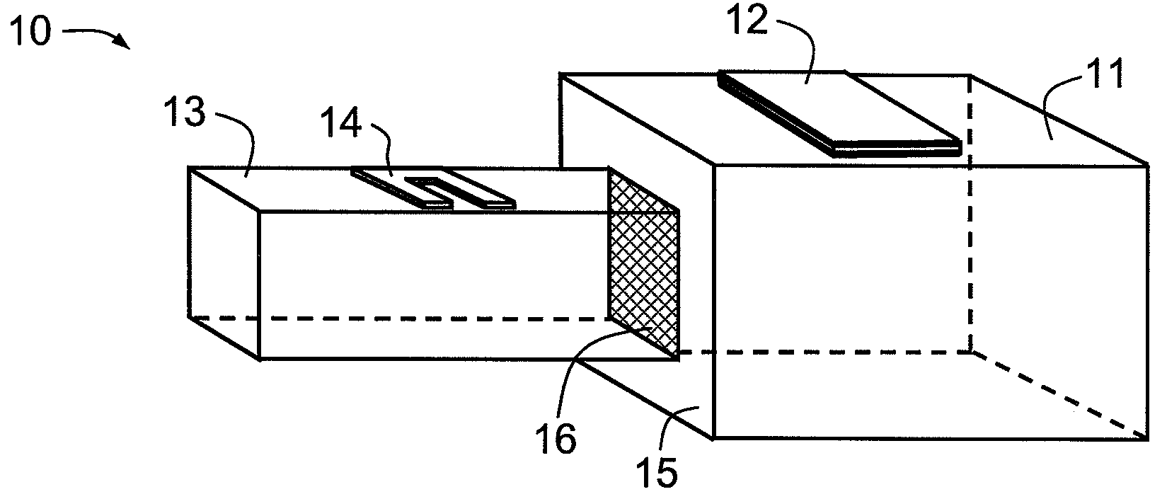
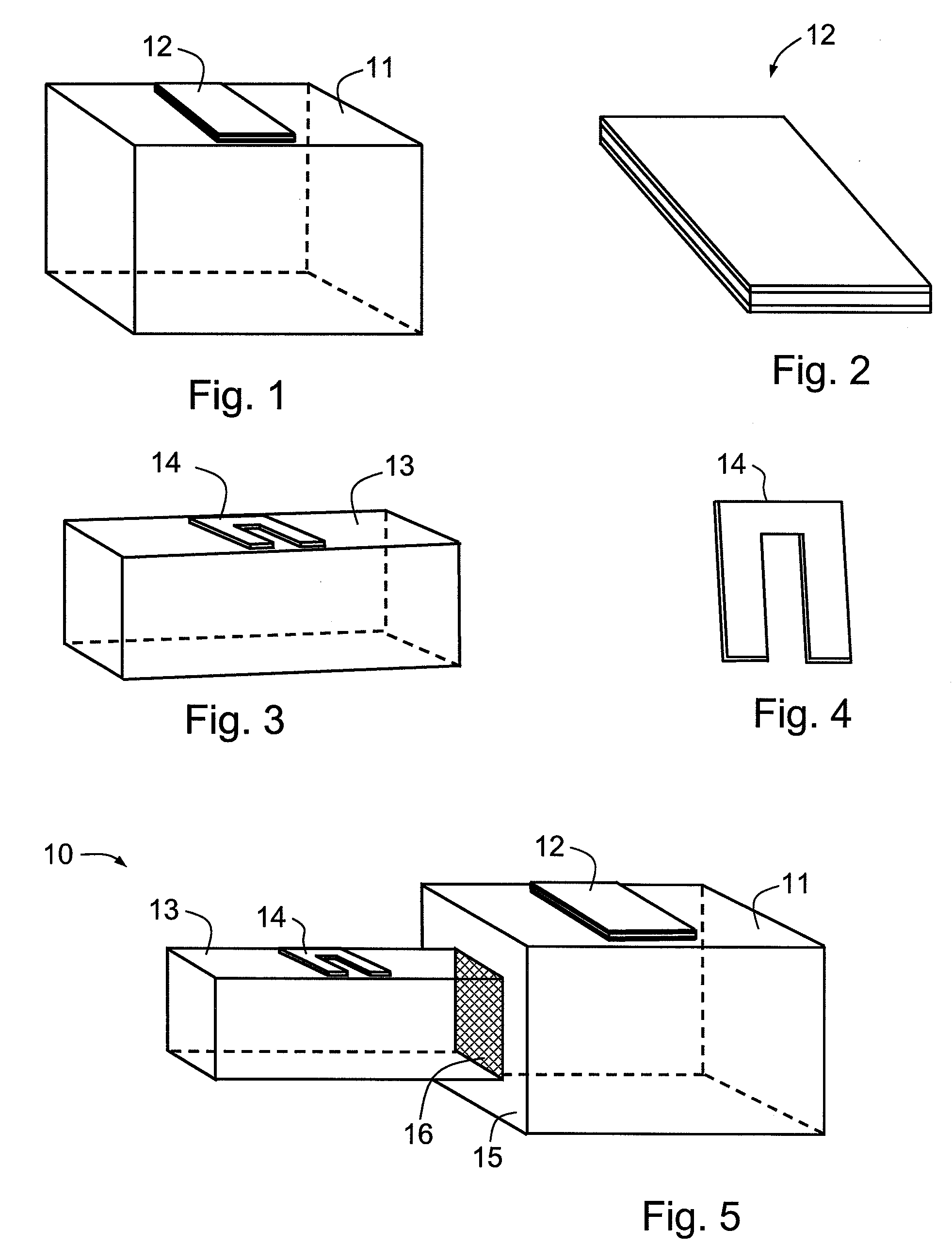
[0035]FIG. 5 is a schematic view of a PEM 10 according to an embodiment of the present invention, comprising a driver block 11 with a piezoelectric transducer 12 and a rectangular optical block 13 with a strain gauge sensor 14. Driver block 11 and optical block 13 have different cross-sectional areas and are joined at step abrupt junction 16. FIG. 9 is a schematic view of a PEM 30 according to another embodiment of the present invention (with transducer and sensor omitted), comprising a driver block 32 and a rectangular optical block 33. Driver block 32 and optical block 33 have the same cross-sectional area and are joined at step abrupt junction 31.

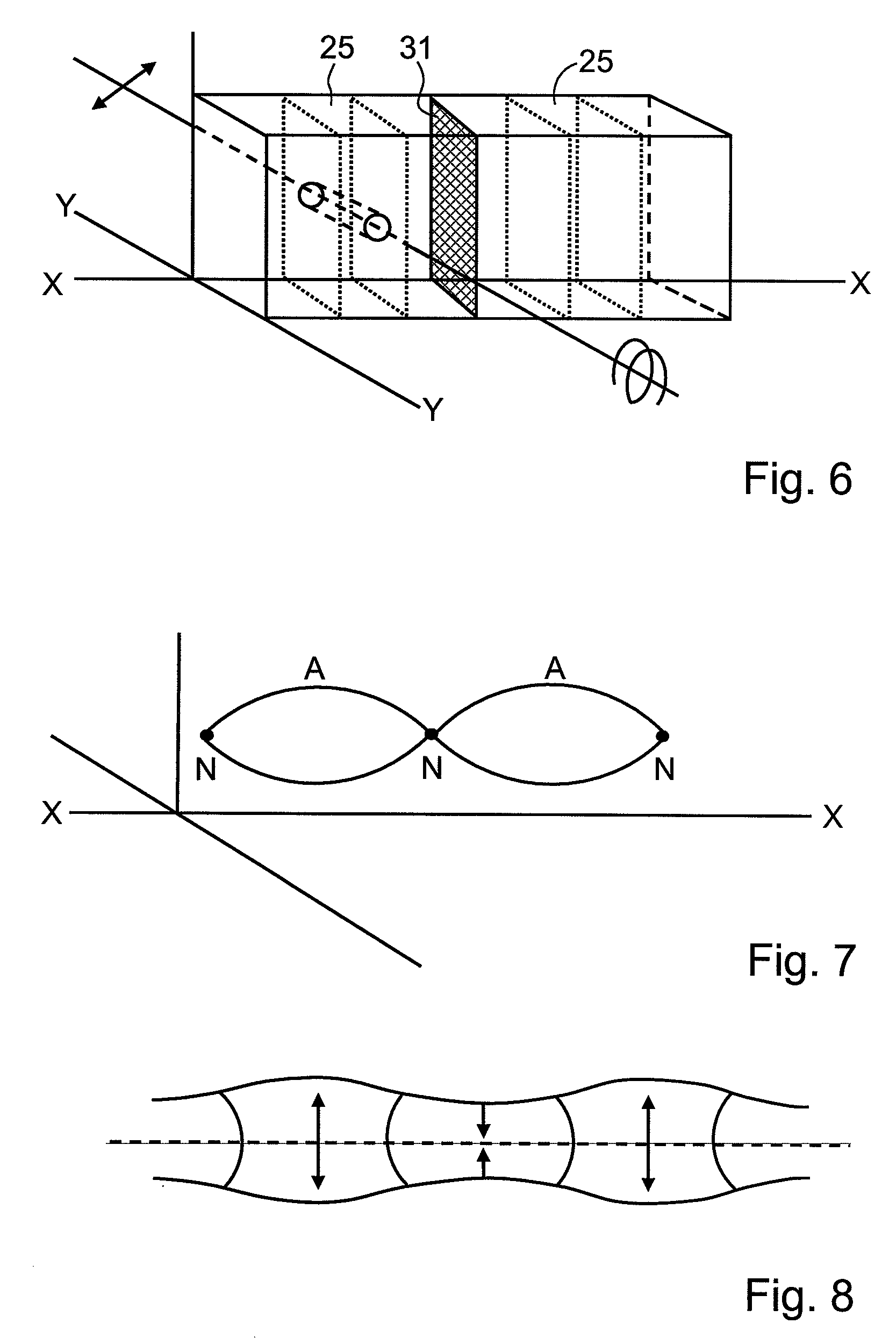
[0036]It is beneficial to define a coordinate system for the PEM blocks and the standing or stationary wave positions. In FIGS. 5 and 9 the major axis of PEMs 10,30 (horizontal from left to right in this view) is the longitudinal acoustic wave propagation axis just before the standing wave is established. As shown in FIG. 6, this axis is...


PUM

PropertyMeasurementUnit
natural frequencyaaaaaaaaaa

Abstract

A photoelastic modulator (PEM) has two parts (11, 13) of the same or dissimilar cross sections, joined together to form an abrupt junction (16). A transducer, for which the natural oscillation is at the half acoustic wavelength mode, excites a longitudinal standing wave of high purity in the PEM. A feedback system is used to achieve stable phase synchronisation of multiple PEMs working at the same oscillation frequency, where the outputs of an amplitude and phase sensor for one PEM is used to correct phase variations of other PEMs and to compensate optical retardation errors.

Description

TECHNICAL FIELD[0001]The invention describes a complete optical modulation system based on the photoelastic effect and is called photoelastic modulator (PEM hereafter). The invention provides highly stable and high precision optical modulation over a wide optical spectral range. In order to achieve stable synchronization of multiple modulators working at the same oscillation frequency with precise phase coherence, a novel method of phase extraction from the oscillating modulator is provided. With this phase synchronization, the application of photoelastic modulators (PEMs) is widely expanded.BACKGROUND TO THE INVENTION[0002]Modern photoelastic modulators (PEM) have been used extensively for scientific and technical measurements of optical quantities related to polarization states and optical birefringence. Examples such as strain inside optically transparent materials, dichroism measurements for the understanding of physical-chemical structures of a wide range of bio-medical and che...

Claims


Application Information

Patent Timeline
Patent Type & Authority Applications(United States)
IPC IPC(8): G02F1/11
CPCG02F1/11G02F2201/16
Inventor LING, WILLIAM P.
Owner ENDEAVOUR INSTR
Why Eureka
Try Eureka