Methods and apparatus for reducing peak-to-rms amplitude ratio in communication signals

a technology of rms amplitude and communication signals, applied in pulse position modulation, pulse technique, baseband system details, etc., can solve the problems of reducing the power spectral density (psd) of the signal, reducing the quality of both standard measures, and reducing the likelihood of receiver errors, so as to reduce the peak-to-rms amplitude ratio without substantially degrading the power spectral density of the signal

Active Publication Date: 2008-12-11
PANASONIC CORP
View PDF24 Cites 17 Cited by
  • Summary
  • Abstract
  • Description
  • Claims
  • Application Information

AI Technical Summary

Benefits of technology

[0012]According to an exemplary method, a pulse or an extra copy of a pulse of a PAM baseband signal is generated to modify the PAM ba

Problems solved by technology

A major disadvantage of the linear amplifier approach is that it degrades the signal quality.
Nonetheless, the conventional (linear amplifier) approach degrades both standard measures of quality, namely an in-band quality measure and an out-of-band quality measur

Method used


Image

  • Methods and apparatus for reducing peak-to-rms amplitude ratio in communication signals
  • Methods and apparatus for reducing peak-to-rms amplitude ratio in communication signals
  • Methods and apparatus for reducing peak-to-rms amplitude ratio in communication signals

Examples


Embodiment Construction

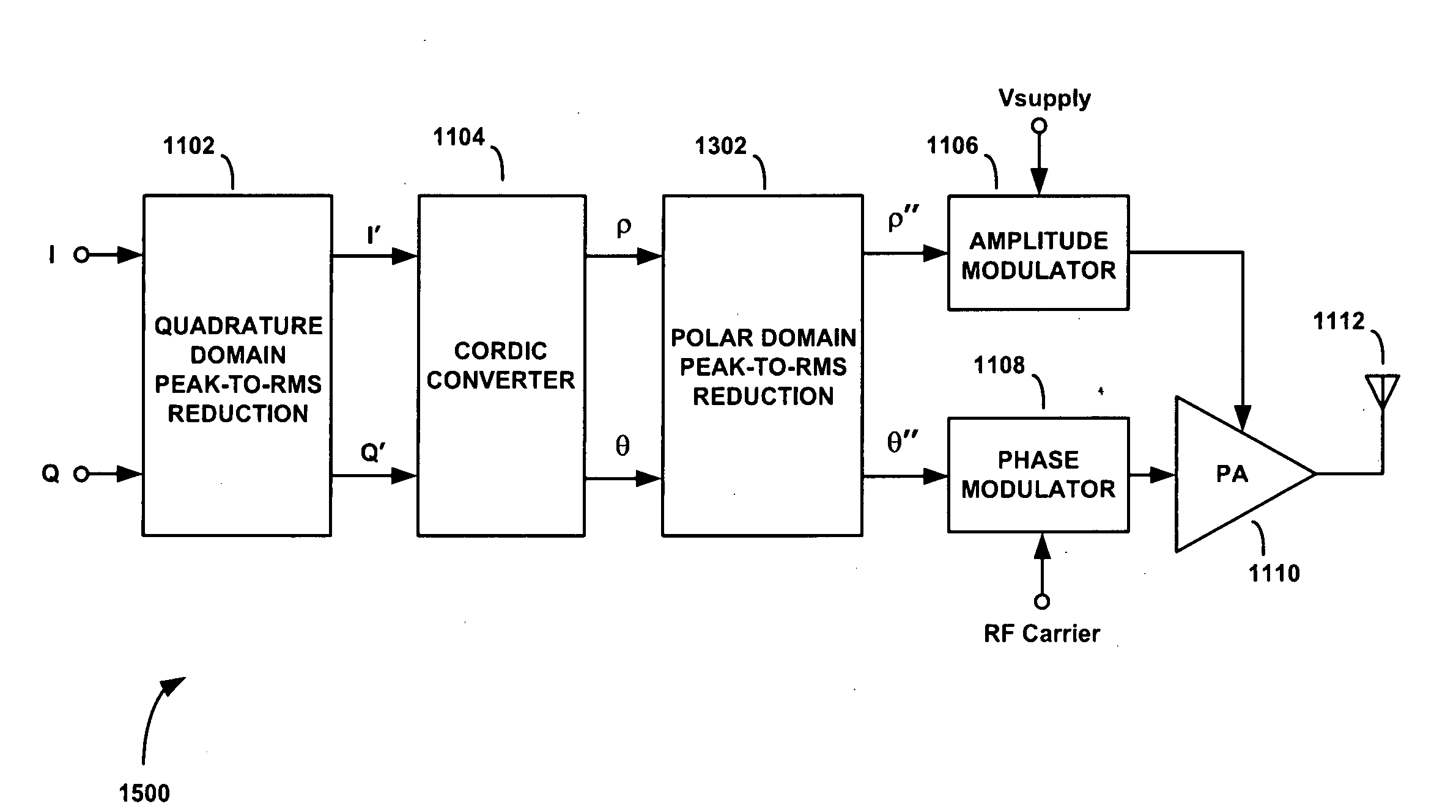
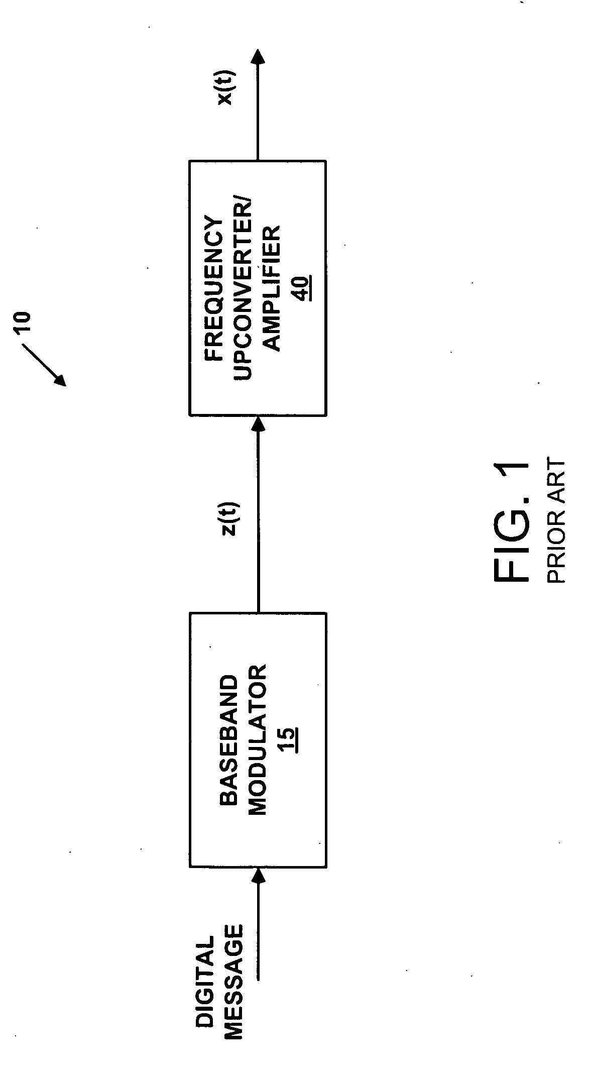
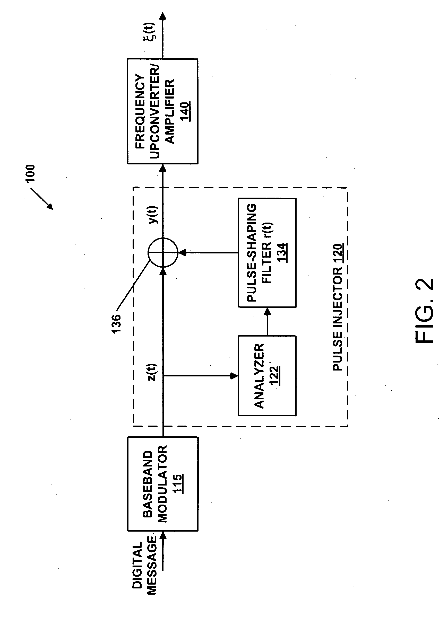
[0033]FIG. 1 is a block diagram of a conventional pulse amplitude modulation (PAM) signal generator 10, which is well known in the prior art. Many modern communication systems transmit digital messages using a scheme called pulse amplitude modulation (PAM). A PAM signal is a frequency-upconverted sum of amplitude-scaled, phase-shifted, and time-shifted versions of a single pulse. The amplitude-scaling and phase-shifting of the nth time-shifted version of the pulse are determined by the nth component of the digital message.

[0034]In the field of communications systems, the broad class of PAM signals includes signals commonly referred to as PAM, quadrature amplitude modulation (QAM) and phase shift keying (PSK), and many variants recognized by those skilled in the art of communications theory. The PAM signal is generated in two parts, namely a baseband modulation process and a frequency-upconversion and amplification process, as illustrated in FIG. 1.

[0035]Referring still to FIG. 1, a ...


PUM


Abstract

A pulse amplitude modulation (PAM) signal generator that injects a copy of a pulse into the PAM baseband signal prior to frequency upconversion and power amplification. The pulse comprises a function of, or an extra copy of, a pulse in the PAM baseband signal. The pulse injector analyzes the PAM baseband signal for times when a predetermined threshold is exceeded and forms a pulse that is constructed and arranged to reduce the amplitude of the PAM baseband signal to a desired peak amplitude when the pulse is added to the PAM baseband signal. In other embodiments the peak-to-RMS amplitude ratio reducing methods and apparatus used to process PAM signal are adapted for reducing peak-to-RMS amplitude ratios of amplitude modulation signals in polar modulation transmitters. Peak-to-RMS amplitude ratio reduction is performed in the quadrature domain, the polar domain, or both the quadrature and polar domains.

Description

CROSS-REFERENCE TO RELATED APPLICATIONS[0001]This application is a continuation-in-part of U.S. application Ser. No. 12 / 042,689, filed Mar. 15, 2008, which claims the benefit of U.S. Provisional Application No. 60 / 906,931, filed Mar. 14, 2007, the disclosures of which are incorporated by reference.FIELD OF THE INVENTION[0002]The present invention relates to pulse amplitude modulation and, more particularly, to a pulse amplitude modulation (PAM) signal generator capable of reducing the peak-to-RMS amplitude ratio of communication signals without spectral degradation.BACKGROUND OF THE INVENTION[0003]Many modern communication systems transmit messages using signals having amplitudes that vary significantly over time. Typically, the power capability of the output device in the transmitter (e.g. the final amplifier) must be selected to accommodate the peak amplitude, or perhaps the amplitude at the 99th percentile, below which 99% of the amplitudes in the signal occur, or perhaps at the ...

Claims


Application Information

Patent Timeline
IPC IPC(8): H04L27/04
CPCH03F1/3247H03F3/24H03F2200/324H03F2200/336H04L25/03343H04L25/03834H04L27/361
Inventor SCHELL, STEPHAN V.BOOTH, RICHARD W O.
Owner PANASONIC CORP
Why Eureka
Try Eureka