Braze or solder reinforced moineu stator

a braze or solder reinforced, moineu stator technology, applied in the direction of machines/engines, manufacturing tools, liquid fuel engines, etc., can solve the problems of cracks, cavities, other types of failure in the lobe, and the elastomer portion of the conventional stator lobe is subject to considerable cyclic deflection, so as to prolong the service life and improve the torque output. , the effect of improving efficiency

Inactive Publication Date:
View PDF34 Cites 53 Cited by
  • Summary
  • Abstract
  • Description
  • Claims
  • Application Information

AI Technical Summary

Benefits of technology

[0013]Exemplary embodiments of the present invention advantageously provide several technical advantages. Exemplary embodiments of this invention address the heat build up and subsequent elastomer breakdown in the lobes of prior arts stators by providing a helical reinforcement component. As such, various embodiments of the Moineau style stator of this invention may exhibit prolonged service life as compared to conventional Moineau style stators. Further, exemplary stator embodiments of this invention may exhibit improved efficiency (and may thus provide improved torque output when used in power sections) as compared to conventional stators including an all elastomer helical cavity component. Moreover solder and / or braze reinforced stators in accordance with this invention are may be constructed with materials that are less likely to damage the rotor.
[0014]Solder and braze reinforced stators of the instant invention are also typically less expensive to fabricate than reinforced stators of the prior art. Methods in accordance with this invention provide for excellent dimensional capability, full thickness of stator walls, and do not reduce the structural integrity of the stator or time-consuming require welding operations.

Problems solved by technology

It has been observed that during operations, the elastomer portions of conventional stator lobes are subject to considerable cyclic deflection, due at least in part to the interference fit with the rotor and reactive torque from the rotor.
Such cyclic deflection is well known to cause a significant temperature rise in the elastomer.
The temperature rise is known to degrade and embrittle the elastomer, eventually causing cracks, cavities, and other types of failure in the lobes.
Such elastomer degradation is known to reduce the expected operational life of the stator and necessitate premature replacement thereof.
Left unchecked, degradation of the elastomer will eventually undermine the seal between the rotor and stator (essentially destroying the integrity of the interference fit), which results in fluid leakage therebetween.
The fluid leakage in turn causes a loss of drive torque and eventually may cause failure of the motor (e.g., stalling of the rotor in the stator) if left unchecked.
However, it has proved difficult to produce suitable elastomer materials that are both (i) rigid enough to prevent distortion of the stator lobes during operation (which is essential to achieving high drilling or pumping efficiencies) and (ii) resilient enough to perform the sealing function at the rotor stator interface.
However, increasing stator length tends to increase fabrication cost and complexity and also increases the distance between the drill bit and downhole logging sensors.
While rigid stators have been disclosed to improve the performance of downhole power sections (e.g., to improve torque output), fabrication of such rigid stators is complex and expensive as compared to that of the above described conventional elastomer stators.
Most fabrication processes utilized to produce long, internal, multi-lobed helixes in a metal reinforced stator are tooling intensive (such as helical broaching) and / or slow (such as electric discharge machining).
As such, rigid stators of the prior art are often only used in demanding applications in which the added expense is acceptable.
The fabrication of composite and rigid elastomer reinforced stators has also proven difficult.
For example, removal of the tooling (the stator core) from the injected composite has proven difficult due to the close fitting tolerances and the thermal mismatches between the materials.
This gap may be formed, for example, by radial shrinkage of the composite material; however, axial shrinkage of the composite can cause interference of the stator core and composite helixes.

Method used


Image

  • Braze or solder reinforced moineu stator
  • Braze or solder reinforced moineu stator
  • Braze or solder reinforced moineu stator

Examples


Embodiment Construction

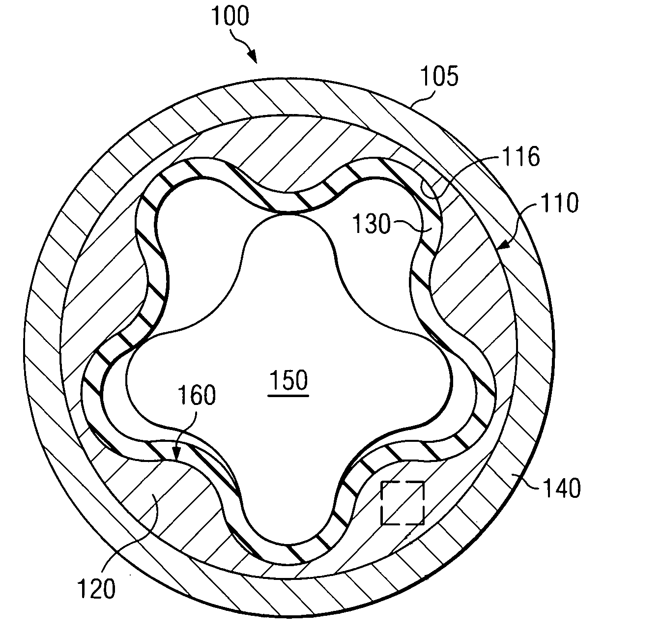
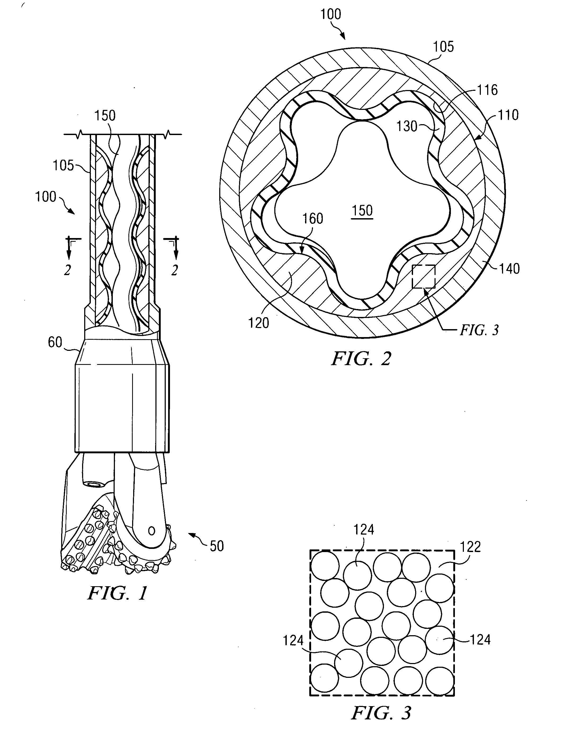
[0023]FIG. 2 depicts a circular cross-section through a Moineau style power section in an exemplary 4 / 5 design. In such a design, the differing helical configurations on the rotor and the stator provide, in circular cross section, 4 lobes on the rotor and 5 lobes on the stator. It will be appreciated that this 4 / 5 design is depicted purely for illustrative purposes only, and that the present invention is in no way limited to any particular choice of helical configurations for the power section design.

[0024]With reference now to FIG. 1, one exemplary embodiment of a Moineau style power section 100 according to this invention is shown in use in a downhole drilling motor 60. Drilling motor 60 includes a helical rotor 150 deployed in the helical cavity of Moineau style stator 105. In the embodiment shown on FIG. 1, drilling motor 60 is coupled to a drill bit assembly 50 in a configuration suitable, for example, for drilling a subterranean borehole, such as in an oil and / or gas formation...


PUM

PropertyMeasurementUnit
particle sizeaaaaaaaaaa
lengthaaaaaaaaaa
volume percentaaaaaaaaaa

Abstract

A Moineau style stator includes a helical reinforcement component that provides an internal helical cavity. A resilient liner is deployed on an inner surface of the helical reinforcement component. The helical reinforcement component includes a solder or braze material and is typically metallurgically bonded to an inner wall of a stator tube. In exemplary embodiments, the helical reinforcement component includes a composite mixture of solder and aggregate. Exemplary embodiments of this invention address the heat build up and subsequent elastomer breakdown in the lobes of prior arts stators by providing a helical reinforcement component. Solder reinforced stators tend to be less expensive to fabricate than reinforced stators of the prior art.

Description

RELATED APPLICATIONS[0001]None.FIELD OF THE INVENTION[0002]The present invention relates generally to positive displacement, Moineau style motors, typically for downhole use. This invention more specifically relates to style stators having helical reinforcement component including a solder material hods for fabricating same.BACKGROUND OF THE INVENTION[0003]Moineau style hydraulic motors and pumps are conventional in subterranean drilling and artificial lift applications, such as for oil and / or gas exploration. Such motors make use of hydraulic power from drilling fluid to provide torque and rotary power, for example, to a drill bit assembly. The power section of a typical Moineau style motor includes a helical rotor disposed within the helical cavity of a corresponding stator. When viewed in circular cross section, a typical stator shows a plurality of lobes in the helical cavity. In most conventional Moineau style power sections, the rotor lobes and the stator lobes are preferably ...

Claims


Application Information

Patent Timeline
Patent Type & Authority Applications(United States)
IPC IPC(8): F01C1/10B23P11/00
CPCF04C2/1075Y10T29/49242Y10T29/49826
Inventor HOOPER, MICHAEL E.ESTEP, JAMES W.QUANTZ, WAYNESYMONDS, DANIELWADE, JOHN CLYDEWHEELER, GLENNON ALLMON
Why Eureka
Try Eureka