Fuel cell stack
a fuel cell and stack technology, applied in the field of fuel cell stacks, can solve the problems of undesired low performance of assembling significant complexity of the structure, and achieve the effects of reducing the overall size and weight of the fuel cell stack, preventing lateral displacement of fuel cells, and simple structur
- Summary
- Abstract
- Description
- Claims
- Application Information
AI Technical Summary
Benefits of technology
Problems solved by technology
Method used
Image
Examples
first embodiment
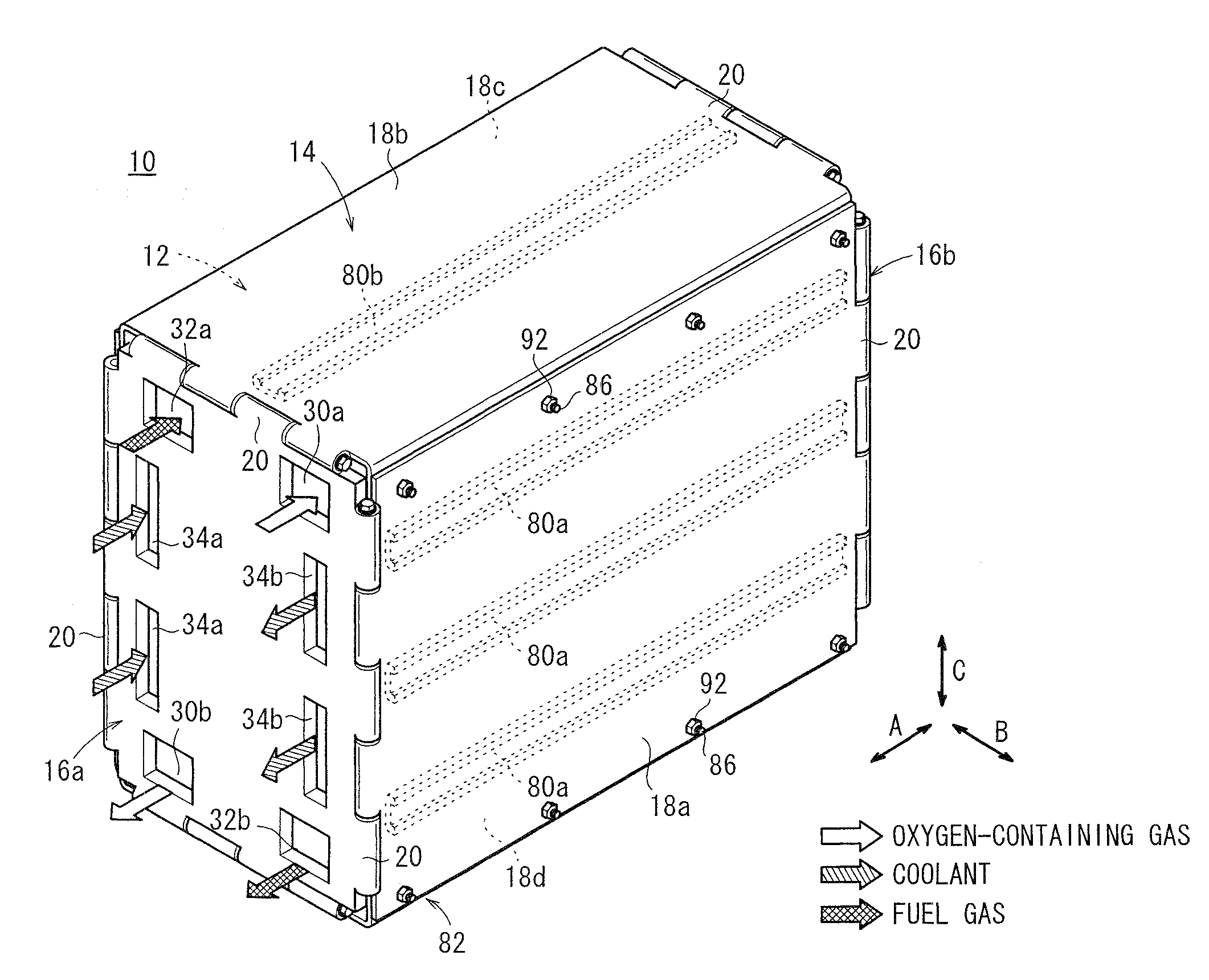
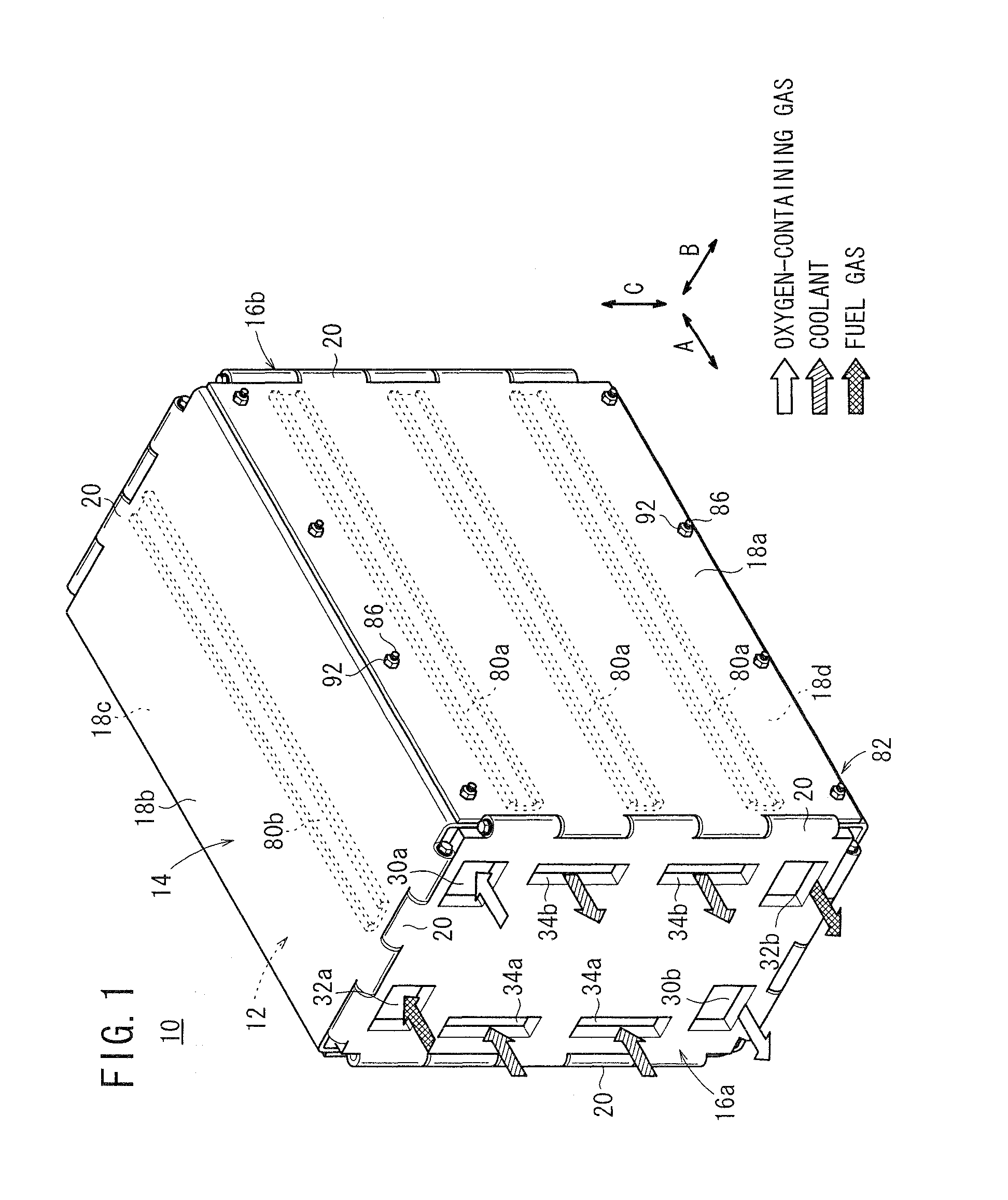
[0031]FIG. 1 is a perspective view schematically showing a fuel cell stack 10 according to the present invention.
[0032]The fuel cell stack 10 includes a plurality of fuel cell units 12 stacked together in a direction indicated by an arrow A and a box 14 containing the fuel cell units 12. The box 14 includes end plates 16a, 16b provided at opposite ends of the fuel cell units 12 in the stacking direction, four side panels (panel members) 18a to 18d provided on sides of the fuel cell units 12, and hinge mechanisms 20 for coupling the end plates 16a, 16b and the side panels 18a to 18d together. The side panels 18a to 18d are made of stainless steel (e.g., SUS 304) or other metal material, or carbon material.
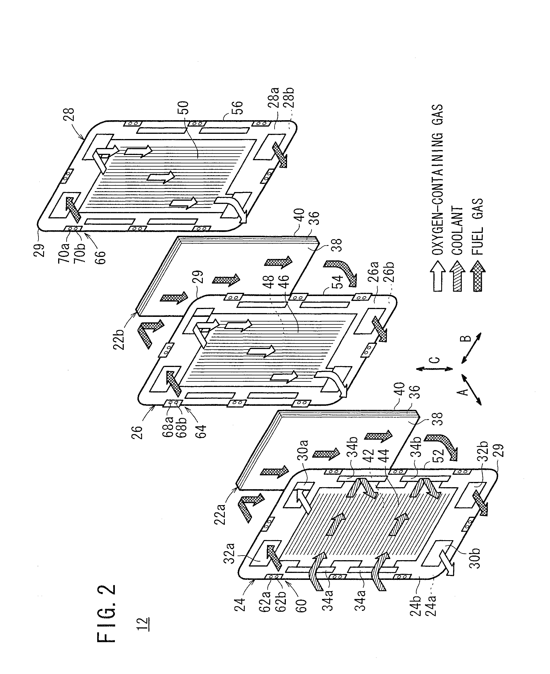
[0033]As shown in FIG. 2, the fuel cell unit 12 includes a first membrane (electrolyte) electrode assembly 22a, a second membrane electrode assembly 22b, a first separator 24, a second separator 26, and a third separator 28. The first membrane electrode assembly 22a is sandwiched be...
second embodiment
[0075]In the second embodiment, when an external load is applied to a side of the fuel cell stack 100, the fuel cell units 102 move toward the side panel 106a, for example.
[0076]Thus, firstly, the load receivers 64 provided in each of the fuel cell units 102 abut against and are supported by the resin receivers 116 of the guide receivers 110. Then, the curved portions 29 abut against and are supported by the pressure receivers 108 of the side panels 106a, 106b. Thus, the external load applied to the side of the fuel cell stack 100 is suitably distributed to the load receivers 64, the resin receivers 116, the curved portions 29, and the pressure receivers 108.
[0077]Accordingly, in the second embodiment, the same advantages as in the case of the first embodiment can be obtained. For example, it is possible to reliably prevent the lateral displacement of the fuel cell units 102, and with the simple structure, reduction in the overall size and weight of the fuel cell stack 100 is achiev...
fourth embodiment
[0083]FIG. 10 is a perspective view schematically showing a fuel cell stack 150 according to the present invention. FIG. 11 is a cross sectional view showing the fuel cell stack 150. The fuel cell stack 150 includes a plurality of fuel cell units 102 stacked in a direction indicated by an arrow A and a box 152 containing the fuel cell units 102. The box 152 includes four side panels (panel members) 154a to 154d provided on four sides of the fuel cell units 102.
[0084]Guide receivers 156 are provided at coupling portions between the side panels 154a to 154d of the box 152, corresponding to load receivers 64 provided at opposite ends in the direction indicated by an arrow B.
[0085]The side panel 154a (one of the panel members) has first protrusions 158a and first recesses 160a at its opposite end surfaces in a direction indicated by an arrow C. The first protrusions 158a and the first recesses 160a are arranged alternately along the stacking direction of the fuel cell units 102 indicate...
PUM
 Abstract
Description
Claims
Application Information
 - R&D
- Intellectual Property
- Life Sciences
- Materials
- Tech Scout
- Unparalleled Data Quality
- Higher Quality Content
- 60% Fewer Hallucinations
Browse by: Latest US Patents, China's latest patents, Technical Efficacy Thesaurus, Application Domain, Technology Topic, Popular Technical Reports.
© 2025 PatSnap. All rights reserved.Legal|Privacy policy|Modern Slavery Act Transparency Statement|Sitemap|About US| Contact US: help@patsnap.com


