Automated tightening shoe

Inactive Publication Date: 2008-12-18
HANDS FREE ENTERPRISES LLC
View PDF5 Cites 134 Cited by
  • Summary
  • Abstract
  • Description
  • Claims
  • Application Information

AI Technical Summary

Benefits of technology

[0016]An automated tightening shoe that tightens snugly around the wearer's foot without use of the wearer's hands, and that can be loosened easily upon demand is provided by this invention. The automated tightening shoe contains a sole and an integral body member or shoe upper constructed of any suitable material. The shoe upper includes a toe, a heel, a tongue, and medial and lateral sidewall portions. A lace or pair of laces is provided for engaging a series of eyelets in a reinforced lacing along the periphery of the medial and lateral uppers. This lace or laces are pulled by the automated tightening mechanism in a crisscrossed fashion across the tongue to draw the medial and lateral shoe uppers around the wearer's foot and snugly against the tongue on top of the wearer's instep. Alternatively, a closure panel secured to the medial shoe upper and extending across the tongue to be pulled to the lateral shoe upper by the automated tightening mechanism, or pulled from both sides by the automated tightening mechanism, may be substi

Problems solved by technology

This can be a hassle for the ordinary wearer.
Moreover, young children may not know how to tie a knot in the shoe lace, thereby requiring assistance from an attentive parent or caregiver.
Furthermore, elderly people suffering from arthritis may find it painful or unduly challenging to pull shoe laces tight and tie knots in order to secure shoes to their feet.
These mechanisms are complicated in their number of parts needed to operate in unison.
However, such tension lever or push plate may not have constant pressure applied to it by the foot, which will result in loosening of the tightening cable or strap.
Moreover, the wearer may find it uncomfortable to step on the tension lever or push plate throughout the day.
But, such a battery-operated device can suffer from short circuits, or subject the wearer to a shock in a wet environment.
But, such Velcro closures can frequently become disconnected when too much stress is applied by the foot.
Moreover, Velcro closures can become worn relatively

Method used


Image

  • Automated tightening shoe
  • Automated tightening shoe
  • Automated tightening shoe

Examples


case bottom 220

[0045]Case bottom 220 as shown in FIG. 7 is preferably molded from RTP 301 polycarbonate glass fiber 10% or functionally equivalent material. Extending from its ends are ears 250 and 252 having threaded screw holes 254 and 256. Case bottom 220 features cut-away portion 260 for accommodating actuator wheel 212. Actuator wheel 212 must be cable of rotating freely without rubbing against case bottom 220. Shoulder surfaces 262 and 263 defined by indents 264 and 265 provide a bearing surface for the ends of axles 242 and 244 and cooperate with case top 222 to secure shaft 224 within the housing provided by case bottom 220 and case top 222. Shoulders 270a, 270b, 270c, and 270d provide additional means of support for the axles 242 and 244. Wells 272 and 274 in case bottom 220 accommodate ratchet wheels 240 and 256 of shaft assembly 240. Finally wells 276 and 278 accommodate engagement cables 190 and 192 as they are wound around axles 242 and 244.

[0046]The underneath side of case top 222 is...

case cap 230

[0051]Case cap 230 is shown in greater detail in FIG. 12. Molded preferably from RTP 301 polycarbonate glass fiber 10% or functionally equivalent material, it features posts 246 and 248 boring through holes 250 and 252, so that screws 232 and 233 can be used to mount case cap 230 to case bottom 220 using screw holes 254 and 256 (see FIG. 7). Axle pegs 316 and 318 of release lever 214 are trapped between indents 260 and 262 of case cap 230 (FIG. 12) and indents 322 and 324 of case top 222, so that release lever 214 may pivot within the automated tightening mechanism. Shoulder 264 along the interior surface of case cap 230 provides an abutment surface for bearing portion 230 of torsion spring 236. Instead of screws, other appropriate fastening means, such as glue or sonic welding may be employed to secure the housing parts of the automated tightening mechanism together.

[0052]In operation, the wearer will position his foot so that actuator wheel 212 extending from the rear of the shoe ...

embodiment 210

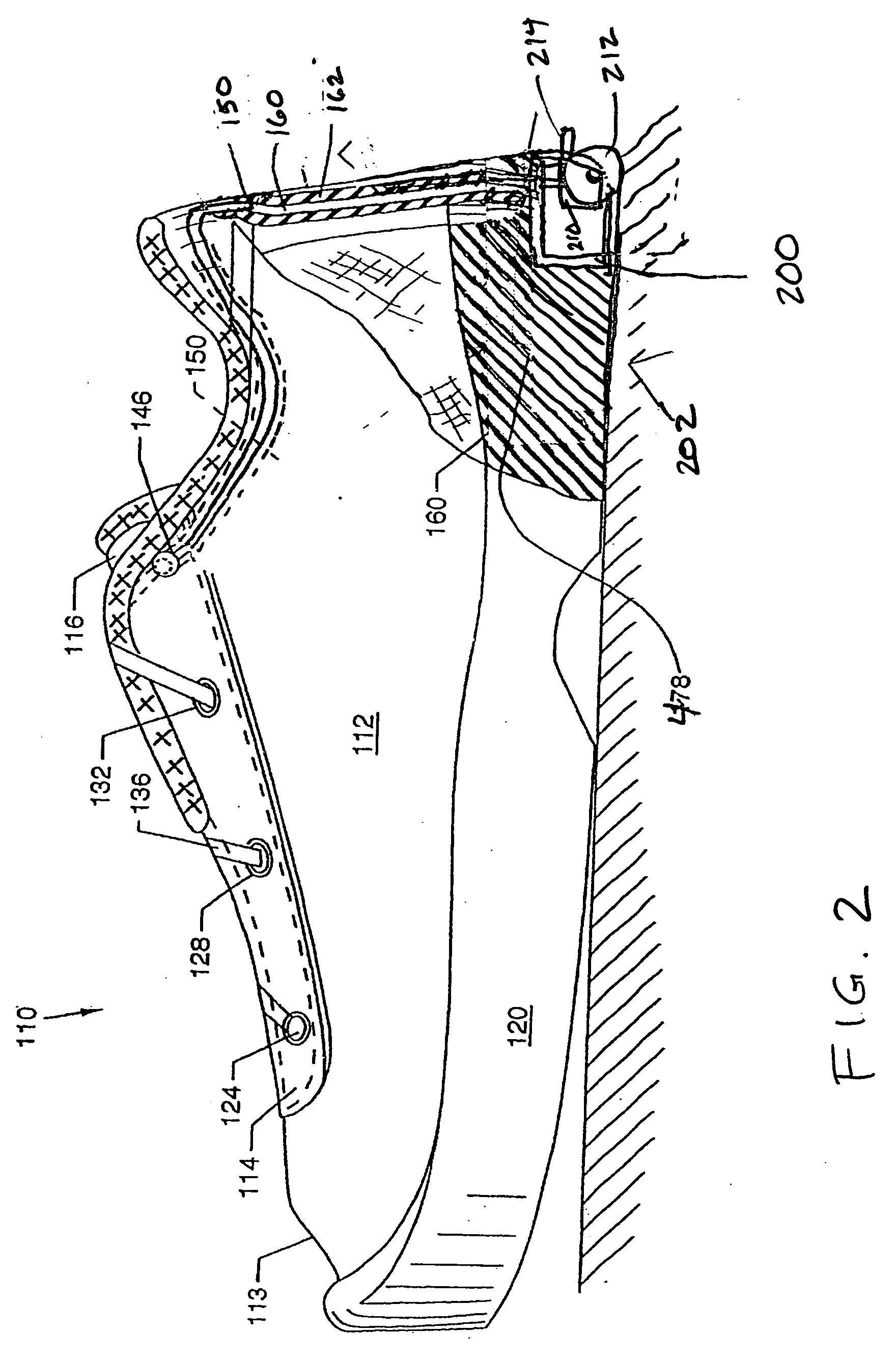
[0054]The automated tightening mechanism 210 of the present invention is simpler in design than other devices known within the industry. Thus, there are fewer parts to assemble during shoe manufacture and to break down during usage of the shoe. Another substantial advantage of the automated tightening mechanism embodiment 210 of the present invention is that shoe laces 136 and 137 and their associated guide tubes may be threaded down the heel portion of the shoe upper, instead of diagonally through the medial and lateral uppers. This feature greatly simplifies manufacture of shoe 110. Moreover, by locating automated tightening mechanism 210 closer to the heel within shoe sole 120, a smaller housing chamber 200 may be used, and the unit may more easily be inserted and glued into a smaller recess within the shoe sole during manufacture.

[0055]Wheel actuator 212 may be any size in diameter as long as it can extend from the shoe sole without interfering with the normal walking or running...


PUM


Abstract

An automated tightening shoe with crisscrossed laces or closure panel and a tightening mechanism which operates in one direction to cause automatic tightening of the crisscrossed laces or closure panel to tighten the shoe about a wearer's foot, and which can be released easily so that the shoe can be removed from the wearer's foot. An actuating wheel partially projecting from the rear sole of the shoe provides a convenient and reliable actuating means for movement of the automated tightening mechanism in the tightening direction.

Description

CROSS-REFERENCE TO RELATED APPLICATION[0001]This application is a continuation-in-part of U.S. Ser. No. 11 / 818,370 filed on Jun. 14, 2007, which is hereby incorporated by reference in its entirety.FIELD OF THE INVENTION[0002]The present invention pertains to a shoe and, more particularly, to an automated tightening shoe. The shoe is provided with an automated tightening system, including a tightening mechanism which operates in one direction to cause automatic tightening of the shoe about a wearer's foot, and which can be released easily so that the shoe can be readily removed from the wearer's foot. The invention is chiefly concerned with an automated tightening shoe of the sport or athletic shoe variety, but the principles of the invention are applicable to shoes of many other types and styles.BACKGROUND OF THE INVENTION[0003]Footwear, including shoes and boots, are an important article of apparel. They protect the foot and provide necessary support, while the wearer stands, walks...

Claims


Application Information

Patent Timeline
IPC IPC(8): A43C11/00
CPCA43B11/00A43C7/04A43C11/165A43C11/14A43C11/008
Inventor JOHNSON, GREGORY G.
Owner HANDS FREE ENTERPRISES LLC
Why Eureka
Try Eureka