Method and sensor for detecting occurrences of wetting on a pane

Inactive Publication Date: 2008-12-18
TRW AUTOMOTIVE ELECTRONICS & COMPONENTS
View PDF12 Cites 0 Cited by
  • Summary
  • Abstract
  • Description
  • Claims
  • Application Information

AI Technical Summary

Benefits of technology

[0003]The present invention provides a method and a sensor for detecting occurrences of wettin

Problems solved by technology

However, the modulation capability is limited by outside ligh

Method used


Image

  • Method and sensor for detecting occurrences of wetting on a pane
  • Method and sensor for detecting occurrences of wetting on a pane
  • Method and sensor for detecting occurrences of wetting on a pane

Examples


Example

[0007]Further features and advantages of the invention will be apparent from the following description of an advantageous embodiment with reference to the enclosed drawings, in which:

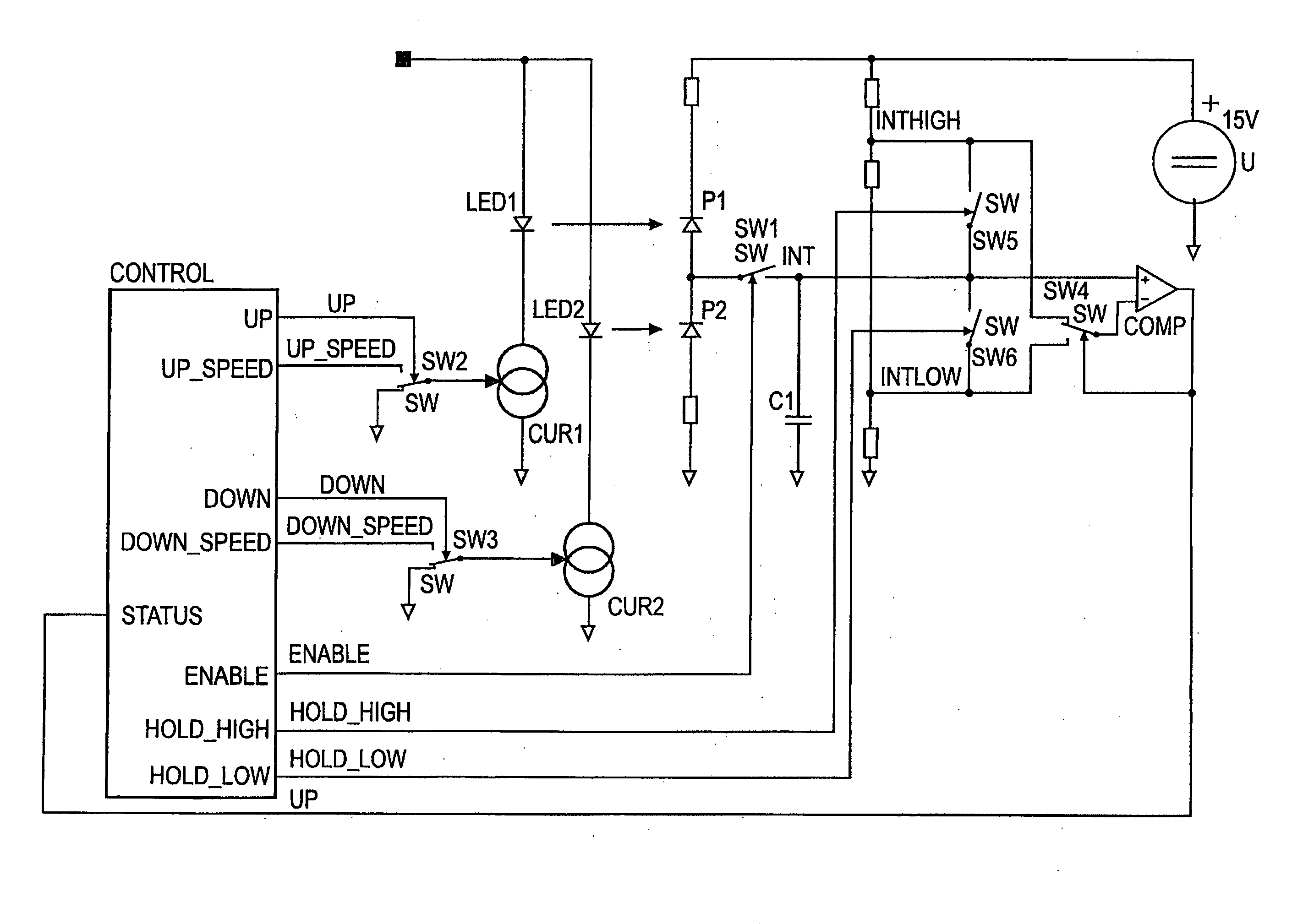
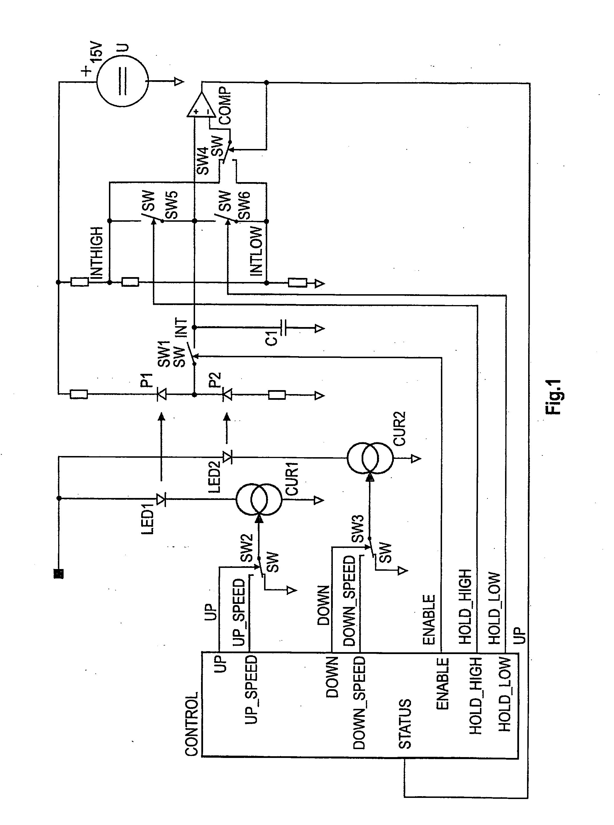
[0008]FIG. 1 shows diagrammatically a circuit diagram of a sensor; and

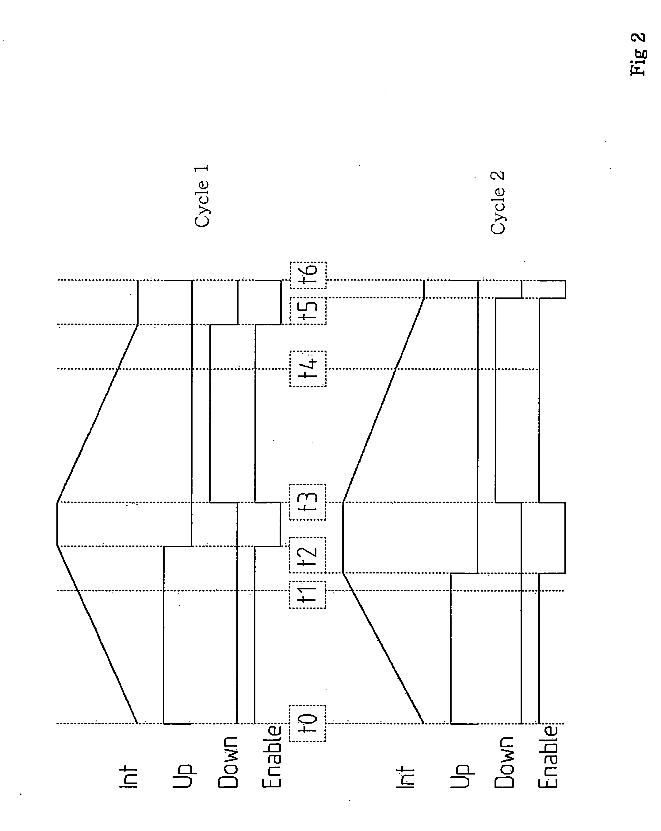
[0009]FIG. 2 shows a signal diagram which illustrates the mode of operation of the sensor.

[0010]The sensor contains two optical measuring sections which are coupled to the inner surface of the pane. The first optical measuring section consists of a light transmitter LED1 in series with a controllable current source CUR1, and a light receiver P1. The second optical measuring section consists of a light transmitter LED2 in series with a controllable current source CUR2, and a light receiver P2. The association between light transmitters and light receivers is symbolized in FIG. 1 respectively by an arrow. The light receivers P1, P2 are arranged in series with each other and with two resistances symmetrically between the two poles of a c...


PUM


Abstract

The method operates with successive, continuously repeated measuring cycles. In a first cycle section, a measuring capacitor is charged up to a first threshold value by the current flowing in a light receiver of a first optical measuring section. In a subsequent, second cycle section the measuring capacitor is discharged to a second threshold value by the current flowing in a light receiver of a second optical measuring section. The light transmitters of the optical measuring sections are regulated over several measuring cycles to predetermined rated values for the charging time and the discharging time. A wetting of the pane is concluded from the momentary deviations between the rated values and the actually measured values of the charging times and discharging times. The available modulation range is adapted dynamically to the prevailing conditions by the systematic control of the intensity of the light transmitters in the two optical measuring sections. In addition, the upper limit of the modulation range is extended to higher values of the ambient light.

Description

BACKGROUND OF THE INVENTION[0001]The invention relates to a method and a sensor for detecting occurrences of wetting on a pane, particularly a rain sensor for vehicles.[0002]Rain sensors have optical measuring sections which contain a light transmitter and a light receiver. Light transmitters and light receivers are coupled to the inner side of the pane so that light emitted from the light transmitter is reflected onto the light receiver by total reflection on the outer surface of the pane. However, the light receiver is also exposed to the ambient light. In order to reduce the influence of the ambient light, two identical optical measuring sections can be used which are arranged adjacent to each other, with the differential signal of the light receivers then being evaluated. However, the modulation capability is limited by outside light and the asymmetry of the optical and electronic components.SUMMARY OF THE INVENTION[0003]The present invention provides a method and a sensor for d...

Claims


Application Information

Patent Timeline
IPC IPC(8): G01W1/14
CPCB60S1/0818G01N21/552G01N2021/435B60S1/08G01N21/00
Inventor BACKES, ULRICH
Owner TRW AUTOMOTIVE ELECTRONICS & COMPONENTS
Why Eureka
Try Eureka