
Evaporative emissions canister with external membrane

a technology of evaporative emissions and canisters, applied in the direction of condensed fuel collection/return, charge feed system, non-fuel substance addition to fuel, etc., can solve the problems of increasing the complexity and cost of the evaporative emissions system, requiring additional space considerations, and using additional canisters

Inactive Publication Date: 2008-12-18
FLUID ROUTING SOLUTIONS
View PDF51 Cites 18 Cited by
  • Summary
  • Abstract
  • Description
  • Claims
  • Application Information

AI Technical Summary

Benefits of technology

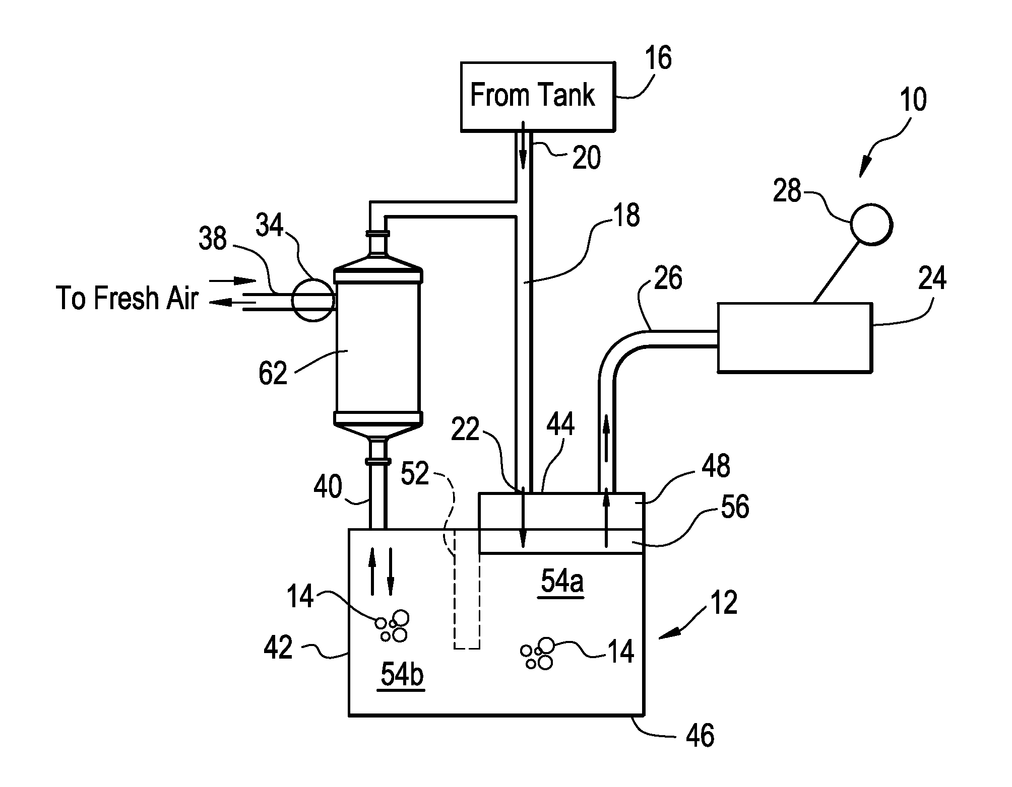
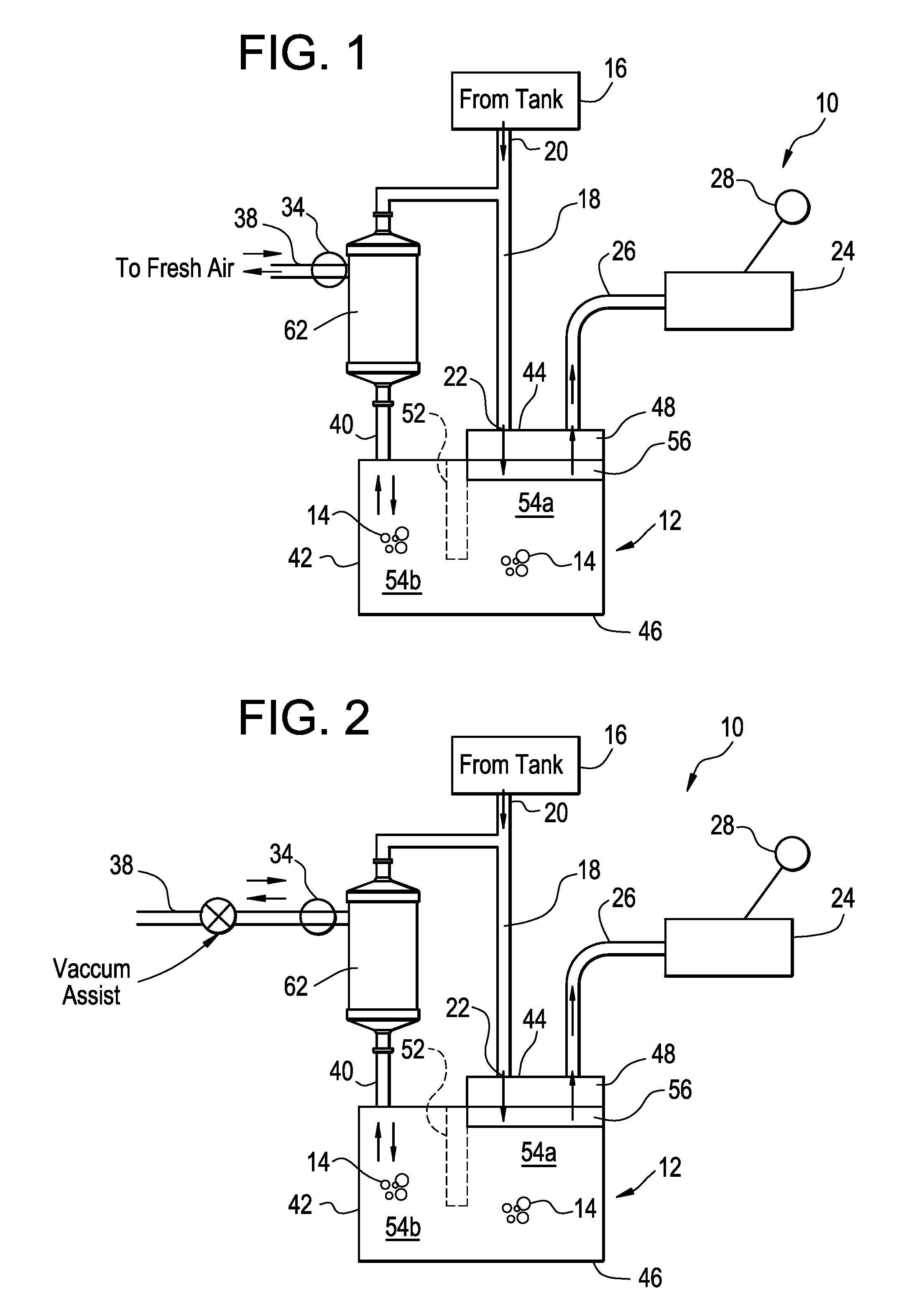
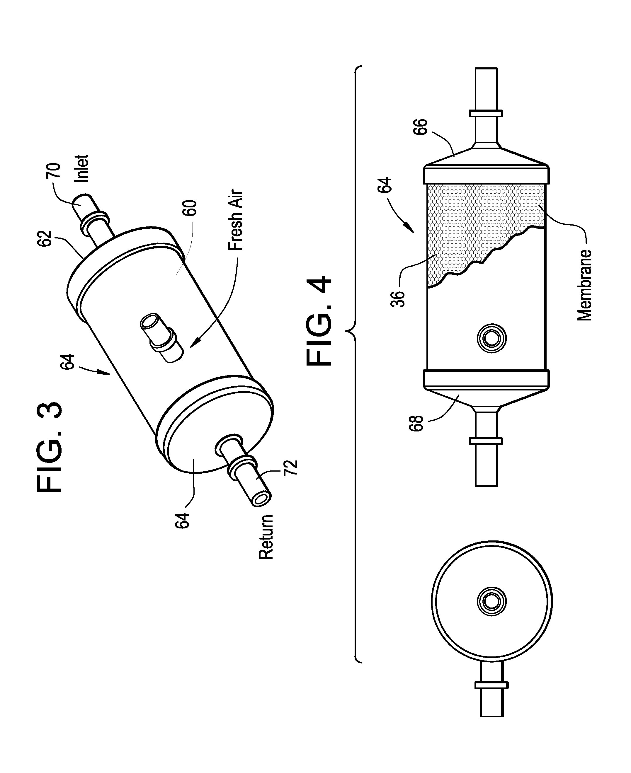
[0006]It has been found that the emission of hydrocarbon fuel pollutants into the atmosphere during fueling of an automotive vehicle, during diurnal changes in the fuel system, and in the operation of such vehicle, can be substantially reduced or eliminated by integrally incorporating a membrane into a device in the fresh air line of the evaporative emissions canister. The device containing the membrane is installed outside the evaporative emissions canister, which allows significant freedom in determining the most efficient configuration and location of the device in the emissions system.
[0008]Accordingly, it is a primary object of this invention to provide an improved evaporative emissions system, which incorporates a membrane in a housing separate from the evaporative emissions canister wherein the full capacity of the adsorbent material can be effectively utilized.
[0010]It is still another object of the invention to optimize the overall packaging of the evaporative emissions system by allowing the membrane housing to be more efficiently configured and located in the emissions system.

Problems solved by technology

As a result of government mandates, automotive manufacturers are constantly being challenged to find better and more efficient ways to prevent or reduce the emissions of hydrocarbon fuel vapors and other pollutants into the atmosphere.
The use of additional canisters not only increase the complexity and cost of the evaporative emissions system, but also requires additional space considerations due to the limited space available in the region of the vehicle wherein a canister is installed.

Method used


Image

  • Evaporative emissions canister with external membrane
  • Evaporative emissions canister with external membrane
  • Evaporative emissions canister with external membrane

Examples


Embodiment Construction

[0017]According to the invention, an evaporative emissions canister such as that described in commonly assigned U.S. patent application Ser. No. 11 / 592,973, filed Nov. 3, 2006, the contents of which are incorporated herein by reference thereto, can be effectively employed to not only reduce the amount of fuel vapor pollutants such as nitrogen oxides, sulfur oxides, etc. into the atmosphere, but to substantially improve the efficiency of the adsorbent material in the evaporative emissions canister by installing a separate housing member containing a membrane wherein the separate housing is installed outside the evaporative emissions canister. In a typical installation, the device is placed in the fresh air line where the membrane permits the free flow of air without obstruction from the atmosphere to the evaporative emissions canister during a purge step, and from the evaporative emissions canister to the atmosphere during a regeneration step, while preventing the emission of hydroca...


PUM


Abstract

An evaporative emissions system is used in an automotive evaporative emission system including a fuel tank coupled to an automotive engine to control emission of fuel vapors to the atmosphere. The system includes (1) an evaporative emissions canister comprising a unitary molded housing having a circumferential side member, a top member and a bottom member; a hydrocarbon-adsorbing material disposed therein so as to provide a vapor adsorbent chamber for adsorbing hydrocarbon fuel vapor flowing therethrough; and (2) a second housing containing a membrane, the second housing located adjacent the fresh air line of the evaporative emissions canister for preventing fuel vapor molecules and pollutants associated therewith, from passing through the membrane while allowing the air molecules to pass therethrough. A method is provided for preventing or substantially reducing hydrocarbon emissions to the atmosphere.

Description

BACKGROUND OF THE INVENTION[0001]The present invention relates to a fuel system for an internal combustion engine; particularly, to a method and an evaporation emissions system for preventing or reducing the emission of hydrocarbon pollutants into the atmosphere; and most particularly, to an advanced evaporative emissions canister having a device containing a membrane which acts as a filter media to prevent or reduce the permeation of hydrocarbon fuel to the atmosphere. The device containing the membrane is external with respect to the evaporative emissions canister.[0002]Evaporative emissions result from any one of several events which includes venting of fuel vapors from the fuel tank due to diurnal changes in ambient pressure and / or temperatures (known in the art as “diurnal” emissions or “bleed” emissions), by refueling of the vehicle (known in the art as “refueling” emissions) or by vaporization of fuel by a hot engine and / or exhaust. Generally, the venting of fuel vapor from t...

Claims


Application Information

Patent Timeline
IPC IPC(8): F02M33/02
CPCF02M33/08F02M25/089
Inventor ALLEN, CHRISTOPHER D.DUMAS, JAMES T.FOSTER, RANDY C.GEPPER, DONALD L.
Owner FLUID ROUTING SOLUTIONS
Learn More