Automatic Velocity Control System For Aircraft

a technology of automatic control and aircraft, which is applied in the direction of vehicle position/course/altitude control, process and machine control, instruments, etc., can solve the problems of causing the initial deceleration caused by sustained or transient gusts to worsen, causing undesirable acceleration and motion effects on passengers, and minimizing the undesirable acceleration encountered by passengers. , the effect of minimizing the undesirable acceleration encountered

Active Publication Date: 2008-12-18
TEXTRON INNOVATIONS
View PDF10 Cites 26 Cited by
  • Summary
  • Abstract
  • Description
  • Claims
  • Application Information

AI Technical Summary

Benefits of technology

[0013]There is a need for an automatic control system for controlling the airspeed of aircraft that minimizes the undesirable accelerations encountered by passengers on the aircraft.
[0014]Therefore, it is an object of the present invention to provide for an automatic control system for controlling the airspeed of aircraft that minimizes the undesirable accelerations encountered by passengers on the aircraft.
[0015]A flight control system for an aircraft receives a selected value of a first parameter, which is either the airspeed or inertial velocity of the aircraft. A primary feedback loop generates a primary error signal that is proportional to the difference between the selected value and a measured value of the first parameter. A secondary feedback loop generates a secondary error signal that is proportional to the difference between the selected value of the first parameter and a measured value of a second flight parameter, which is the other of the airspeed and inertial velocity. The primary and secondary error signals are summed to produce a velocity error signal, and the velocity error signal and an integrated value of the primary error signal are summed to produce an actuator command signal. The actuator command signal is then used for operating aircraft devices to control the first parameter to minimize the primary error signal. o The present invention provides for several advantages, including: (1) reduction of unwanted longitudinal acceleration caused by automatic responses to head-on gusts and air turbulence; (2) reduction of the automatic engine power changes caused as a response to air turbulence; (3) increase of the stability for a flight control system, thus reducing the overshoots and undershoots caused by turbulence and commanded changes; and (4) improvement of the efficiency of the aircraft by reducing accelerations caused by the air turbulence.

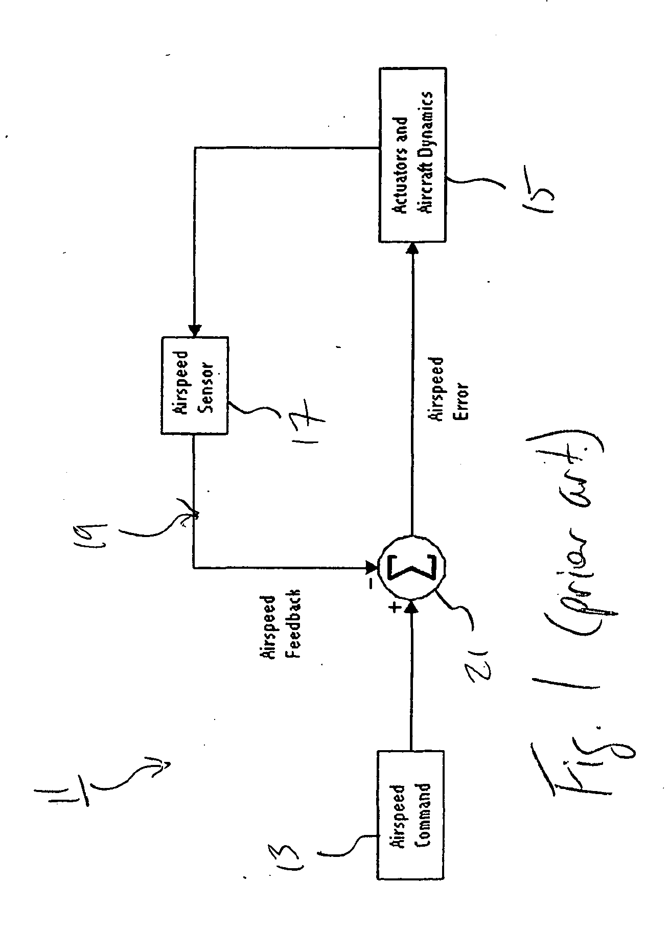
Problems solved by technology

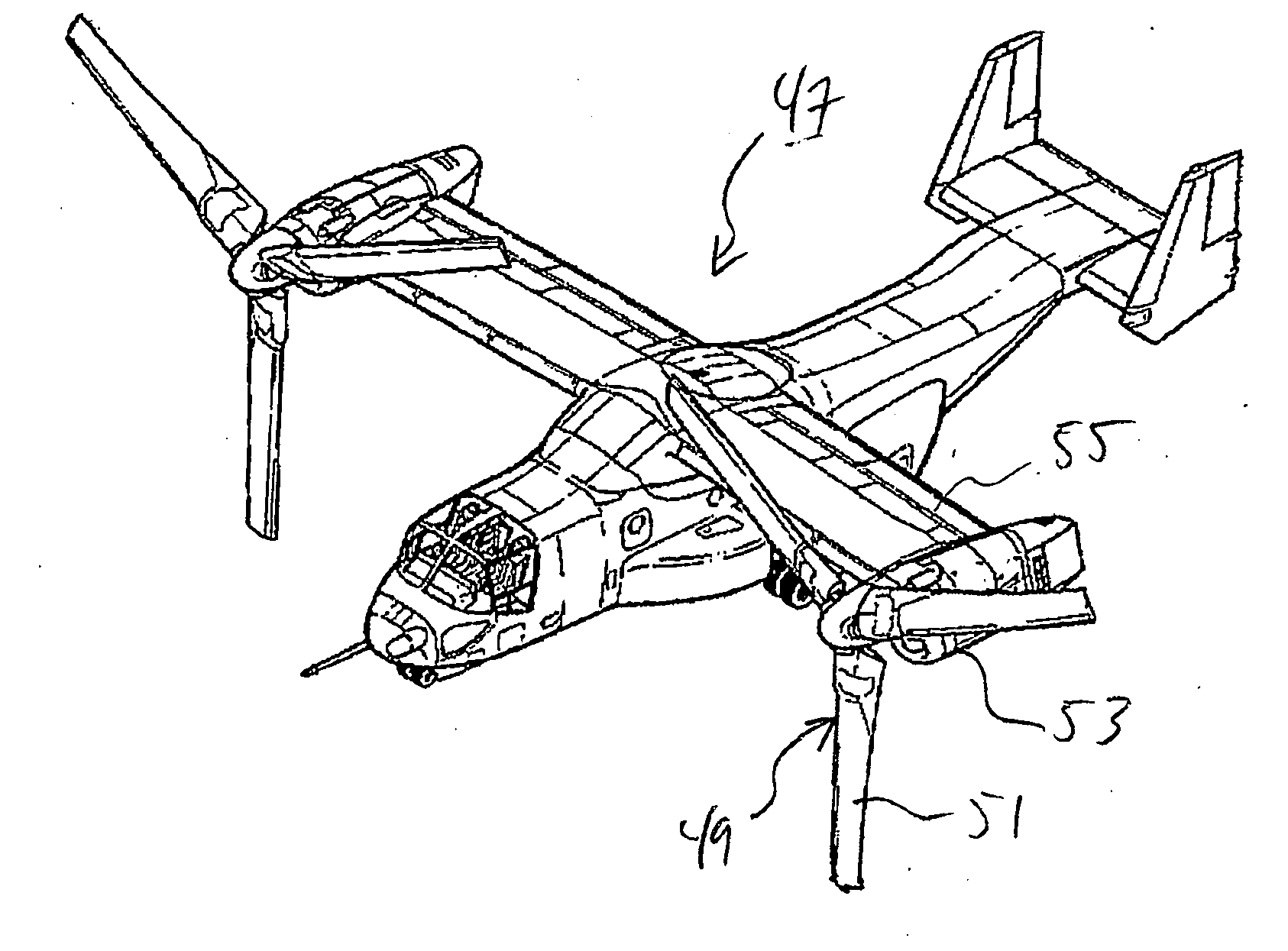
Changes in engine power and pitch attitude are transmitted into the cabin of the aircraft, producing undesirable acceleration and motion effects on passengers.
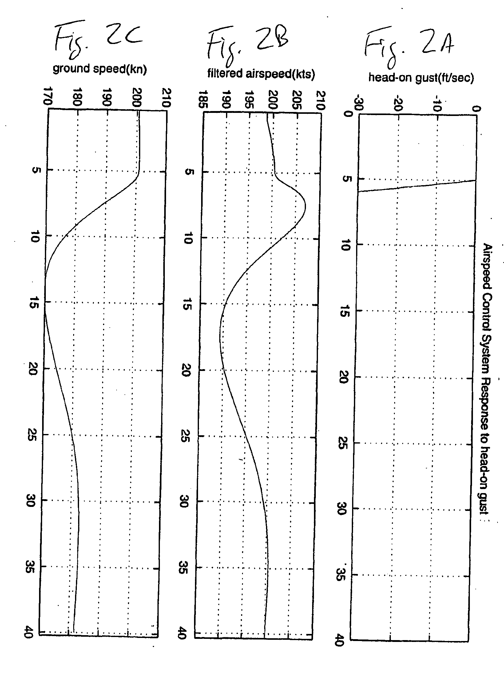
The combination of the positive and negative accelerations due to the behavior of system 11 causes undesirable effects on the passengers of the aircraft.
The initial deceleration caused by a sustained or transient gust is worsened by the accelerations due to the large undershoot and overshoot of the throttle position.

Method used


Image

  • Automatic Velocity Control System For Aircraft
  • Automatic Velocity Control System For Aircraft
  • Automatic Velocity Control System For Aircraft

Examples


Embodiment Construction

[0025]The present invention is directed to an airspeed control system configured for automatically controlling the airspeed of an aircraft and reducing the longitudinal accelerations due to air turbulence encountered during flight. When a wind gust having a longitudinal component is detected, the system of the invention uses the combination of an airspeed signal and an inertial velocity (longitudinal ground speed) signal as the velocity feedback signal for the control system. In calm air, the steady-state airspeed and inertial velocity are the same value.

[0026]Referring to the figures, FIG. 4 shows a schematic view of a preferred embodiment of the control system of the invention in which a selected airspeed is commanded by the operator or pilot. System 23 is a closed-loop feedback system that uses both airspeed and inertial velocity (ground speed) to determine the appropriate throttle response to changes in airspeed. In the system shown, a selected airspeed signal is output from a c...


PUM


Abstract

A flight control system for an aircraft receives a selected value of a first parameter, which is either the airspeed or inertial velocity of the aircraft. A primary feedback loop generates a primary error signal that is proportional to the difference between the selected value and a measured value of the first parameter. A secondary feedback loop generates a secondary error signal that is proportional to the difference between the selected value of the first parameter and a measured value of a second flight parameter, which is the other of the airspeed and inertial velocity. The primary and secondary error signals are summed to produce a velocity error signal, and the velocity error signal and an integrated value of the primary error signal are summed to produce an actuator command signal. The actuator command signal is then used for operating aircraft devices to control the first parameter to minimize the primary error signal.

Description

TECHNICAL FIELD[0001]The present invention relates generally to the field of flight control systems for aircraft and relates particularly to a system for automatically controlling the velocity of an aircraft.DESCRIPTION OF THE PRIOR ART[0002]Many modern aircraft have flight control systems for maintaining selected flight parameters at or near selected values. These parameters may include altitude, heading, attitude, and / or airspeed, and the control system maintains each parameter by operating flight control systems of the aircraft. For example, altitude may be controlled through use of flight control surfaces, such as elevators, or through use of the throttle to control the airspeed of the aircraft. These flight control systems are usually closed-loop feedback control systems, allowing for the input from the control system to respond to changes in the controlled parameter.[0003]Typical closed-loop systems control the velocity of the aircraft using either the airspeed or the inertial...

Claims


Application Information

Patent Timeline
Patent Type & Authority Applications(United States)
IPC IPC(8): G05D1/08B64C1/00
CPCB64D31/08G05D1/0615
Inventor BUILTA, KENNETH E.SCHULTE, KYNN J.
Owner TEXTRON INNOVATIONS
Why Eureka
Try Eureka