Antenna Using Proximity-Coupling Between Radiation Patch and Short-Ended Feed Line, Rfid Tag Employing the Same, and Antenna Impedance Matching Method Thereof

a technology of proximity coupling and radiation patch, which is applied in the direction of resonant antennas, burglar alarm mechanical actuation, instruments, etc., can solve the problems of miniaturization and production cost of the method using the matching circuit, and the limitation of the transmission power of the rfid reader. achieve excellent performan

Inactive Publication Date: 2008-12-18
ELECTRONICS & TELECOMM RES INST
View PDF14 Cites 32 Cited by
  • Summary
  • Abstract
  • Description
  • Claims
  • Application Information

AI Technical Summary

Benefits of technology

[0024]The technology of the present invention provides an antenna that can freely control the resistance and reactance of antenna impedance independently from each other by disposing a short-ended microstrip feed line that is formed in a resonance length direction of a radiation patch between the radiation patch and a ground plate. Also, the present invention provides a plannar antenna that has a resonance characteristic and can be matched to an antenna connection element having a predetermined impedance level efficiently in wide bands by proximity-coupling the feed line with the radiation patch, and a radio frequency identification (RFID) tag employing the antenna.
[0025]The antenna based on proximity coupling with a short-ended feed line and the RFID tag employing the antenna have resonance and wideband characteristics, and they can provide excellent performance even when they are attached to a metal surface or an object having a high dielectric rate. In addition, the present invention provides a method of matching impedance of the antenna.

Problems solved by technology

However, since the transmission power of an RFID reader is regulated by the U.S. Federal Communication Commission (FCC) and local regulations, there is limitation in raising the transmission power of an RFID reader.
However, since the matching circuit composed of a capacitor and an inductor requires much space in a chip, the method using a matching circuit has a problem in the respect of miniaturization and production cost.

Method used


Image

  • Antenna Using Proximity-Coupling Between Radiation Patch and Short-Ended Feed Line, Rfid Tag Employing the Same, and Antenna Impedance Matching Method Thereof
  • Antenna Using Proximity-Coupling Between Radiation Patch and Short-Ended Feed Line, Rfid Tag Employing the Same, and Antenna Impedance Matching Method Thereof
  • Antenna Using Proximity-Coupling Between Radiation Patch and Short-Ended Feed Line, Rfid Tag Employing the Same, and Antenna Impedance Matching Method Thereof

Examples


first embodiment

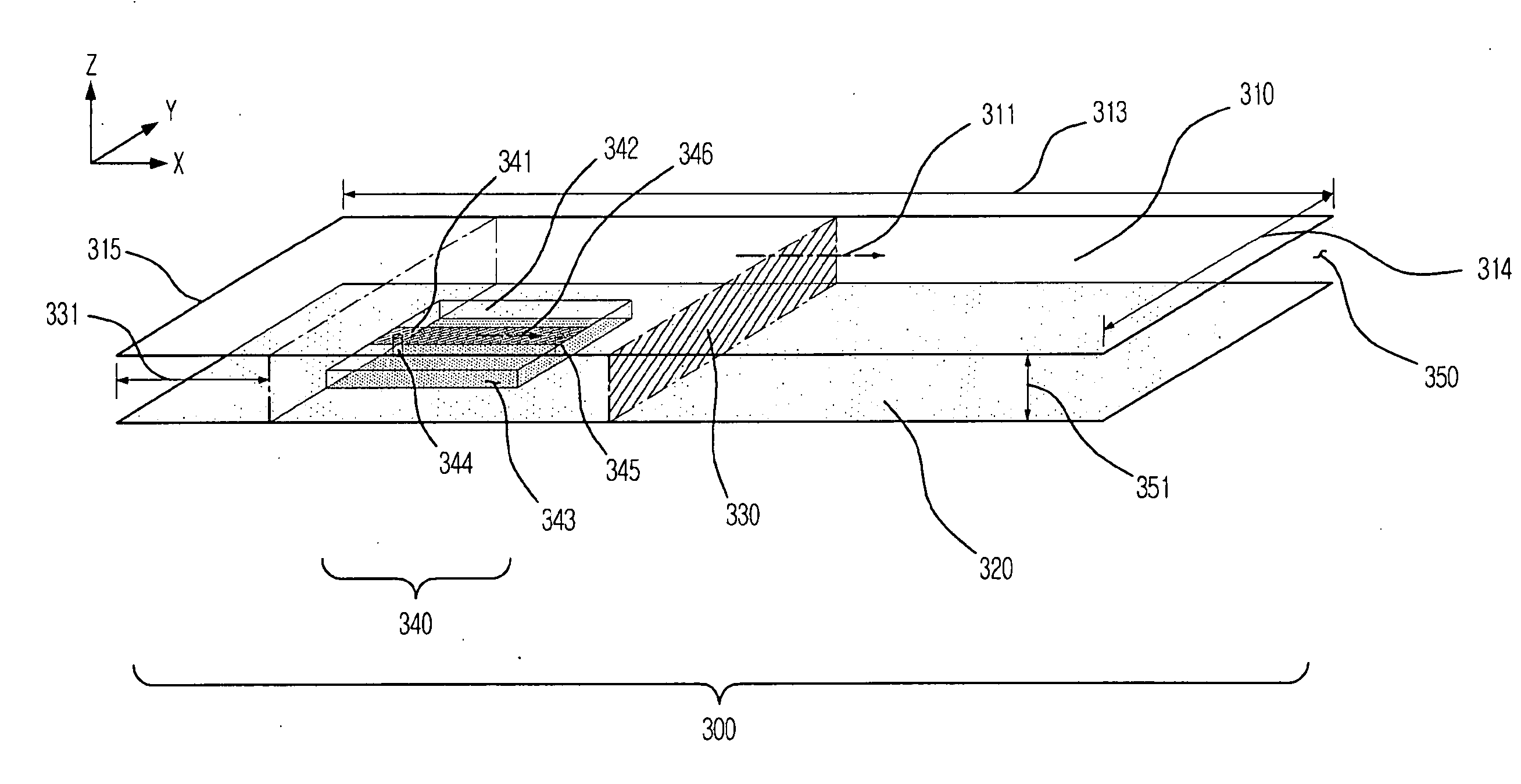
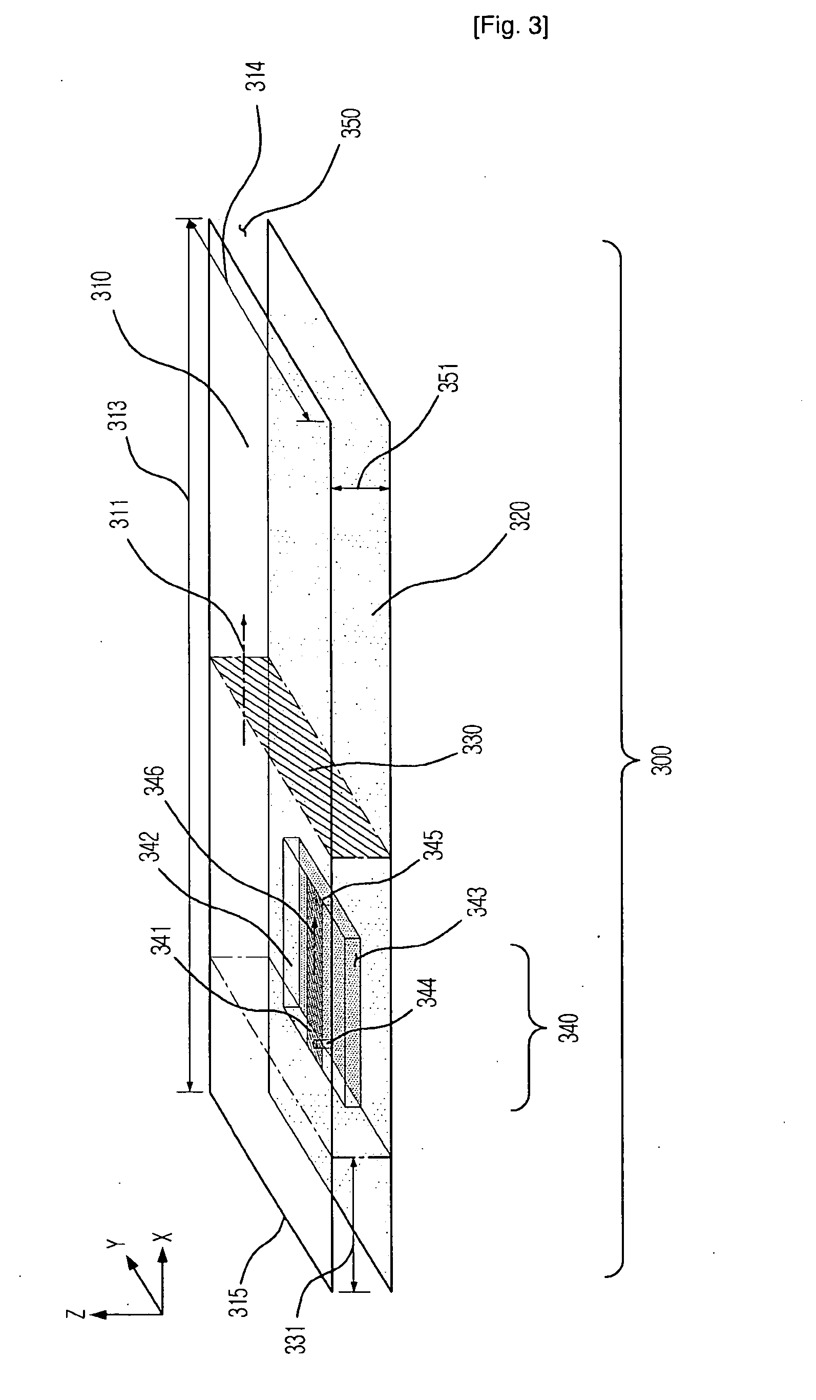
[0047]FIG. 3 is a perspective view showing a tag antenna in accordance with the present invention. The tag antenna 300 includes a rectangular radiation patch 310 and a ground plate 320 disposed in parallel to the radiation patch 310. The radiation patch 310 is proximity-coupled with a microstrip feed line 341.

[0048]The feeding part 340 of the tag antenna 300 includes a dielectric substrate 342 disposed between the radiation patch 310 and the ground plate 320, the microstrip feed line 341 disposed in one side of the dielectric substrate 342, and the ground surface 343 disposed in the other side of the dielectric substrate 342. The feeding part 340 is interposed between the radiation patch 310 and the ground plate 320, and the ground surface 343 of the feeding part 340 is connected to the ground plate 320 in direct current (DC) or in alternating current (AC) through capacitive coupling. The ground surface 343 connected to the ground plate 320 in alternating current can be fabricated b...

second embodiment

[0062]FIG. 4 is a perspective view showing a tag antenna in accordance with the present invention. The tag antenna 400 of FIG. 4 reduces the length 413 of the radiation patch 410 by additionally including the shorting plate 430 between the radiation patch 410 and the ground plate 42 to connect the radiation patch 410 and the ground plate 420 with each other. The shorting plate 430 is set up perpendicularly to a resonance length direction 41 at the brim in opposite to the tag chip feed 444 in the radiation patch 410. The width 431 of the shorting plate 430 may be different from the width 414 of the radiation patch 410. In FIG. 4, the input impedance of the tag antenna 400 is controlled in the same method as in FIG. 3.

third embodiment

[0063]FIG. 5 is a perspective view showing a tag antenna in accordance with the present invention. The tag antenna 500 reduces the length 513 of the radiation patch 510 by additionally disposing shorting pins 530 between the radiation patch 510 and the ground plate 520 to connect the radiation patch 510 with the ground plate 520. The shorting pins 530 are set up perpendicularly to the resonance length direction at the brim in opposite to the tag chip feed in the radiation patch 510. The input impedance of the tag antenna 500 shown in FIG. 5 is controlled in the same method as in FIG. 3.

[0064]Also, the tag antenna 500 of FIG. 5 has a small feeding part 540 by forming the feed line 541 in a meander structure. The feed lines 341 and 441 of the tag antennas 300 and 400 illustrated in FIGS. 3 and 4 have a straight line shape. However, the feed lines 341 and 441 may be fabricated in diverse structures widely known to those skilled in the art of the present invention, which includes the me...


PUM


Abstract

Provided is an antenna based on proximity coupling between a short-ended microstrip feed line and a radiation patch, an RFID tag including the planar antenna, and an antenna impedance matching method thereof. The antenna includes a radiation patch configured to determine a resonant frequency of the antenna; a ground plate disposed in parallel to the radiation patch; and a feeding part disposed between the radiation patch and the ground plate and configured to provide radio frequency signals to a device connected to the antenna. The feeding part includes a feed line that is formed in a resonance length direction of the radiation patch and proximity-coupled with the radiation patch and one end of the feed line is shorted. The antenna freely controls the resistance and reactance of the antenna impedance independently and efficiently matched to a device connected to the antenna which has a predetermined impedance in wide bands.

Description

TECHNICAL FIELD[0001]The present invention relates to an antenna, a radio frequency identification (RFID) tag employing the antenna, and an antenna impedance matching method thereof; and, more particularly, to a planar antenna based on proximity coupling between a short-ended microstrip feed line and a radiation patch, an RFID tag, or a transponder, which includes the planar antenna, and an antenna impedance matching method thereof.BACKGROUND ART[0002]A radio frequency identification (RFID) tag is used in diverse areas, such as material management and security, along with an RFID reader, or an interrogator. In general, when an object with an RFID tag attached thereto is placed in a read zone of an RFID reader, the RFID reader modulates RFID signals having a predetermined carrier frequency to thereby produce interrogation signals and transmits the interrogation signals to the RFID tag. The RFID makes a response to the interrogation of the RFID reader.[0003]In other words, the RFID re...

Claims


Application Information

Patent Timeline
Patent Type & Authority Applications(United States)
IPC IPC(8): H01Q1/38H01Q1/50G08B13/14
CPCH01Q1/2208H01Q9/0421
Inventor SON, HAE-WONCHOI, WON-KYUCHOI, GIL-YOUNGPYO, CHEOL-SIGCHAE, JONG-SUK
Owner ELECTRONICS & TELECOMM RES INST
Why Eureka
Try Eureka