
Method of Generating Lower Layer Data Block in Wireless Mobile Communication System

a wireless mobile communication system and data block technology, applied in the field of wireless mobile communication system, can solve the problems of serious transmission efficiency reduction, inability to completely reduce the transmission of status pdu or piggyback status pdu, and the padding bit cannot be generated no matter, so as to increase the efficiency of controlling information transmission efficiency, the maximum user data rate, and the effect of increasing the efficiency of using limited resources by the transmitting and receiving sides

Inactive Publication Date: 2008-12-18
LG ELECTRONICS INC
View PDF10 Cites 19 Cited by
  • Summary
  • Abstract
  • Description
  • Claims
  • Application Information

AI Technical Summary

Benefits of technology

[0061]An object of the present invention is to provide a method of generating a data block, by which efficiency in using limited resources by layers of transmitting and receiving sides in a wireless mobile communication system can be raised.
[0062]Another object of the present invention is to provide a method of generating a data block, by which a maximum user data rate can be achieved in a wireless mobile communication system.
[0063]Another object of the present invention is to provide a method of generating a data block, by which control information transmission efficiency can be increased in a wireless mobile communication system.
[0064]Another object of the present invention is to provide a transmitter and receiver, by which a maximum user data rate is achieved in a manner of raising efficiency in using limited resources in a wireless mobile communication system and by which control information transmission efficiency is increased.
[0065]A further object of the present invention is to provide a data block structure, by which a maximum user data rate is achieved in a manner of raising efficiency in using limited resources in a wireless mobile communication system and by which control information transmission efficiency is increased.

Problems solved by technology

Yet, in data transmission of AM RLC, since a transmitting side always needs acknowledgement indicating that data is correctly received from a receiving side, it is unable to completely reduce the transmission of the status PDU or the piggybacked status PDU.
Yet, since it is assumed that the AM RLC has sufficient user data to be transmitted, a padding bit cannot be generated no matter how the AMD PDU is configured.
First of all, in spite that there is sufficient data to be transmitted by AM RLC, in case that a size of status report is smaller than that of AMD PDU, a padding bit having no significance as information, as shown in FIG. 7, exists in a status PDU. This means a serious transmission efficiency reduction in case that there are excessive user data to be transmitted by the AM RLC.
Yet, in the related art, the piggybacked status PDU is not facilitated to use.
However, in the related art, a size of a piggybacked status PDU is limited to a space remaining after AMD PDU is filled up with at least one SDU.
So, even if AM RLC needs to use the piggybacked status PDU, it is frequently unable to use the corresponding PDU.

Method used


Image

  • Method of Generating Lower Layer Data Block in Wireless Mobile Communication System
  • Method of Generating Lower Layer Data Block in Wireless Mobile Communication System
  • Method of Generating Lower Layer Data Block in Wireless Mobile Communication System

Examples


Embodiment Construction

[0096]Reference will now be made in detail to the preferred embodiments of the present invention, examples of which are illustrated in the accompanying drawings.

[0097]FIG. 9 is a diagram of a method of generating a data block according to one preferred embodiment of the present invention.

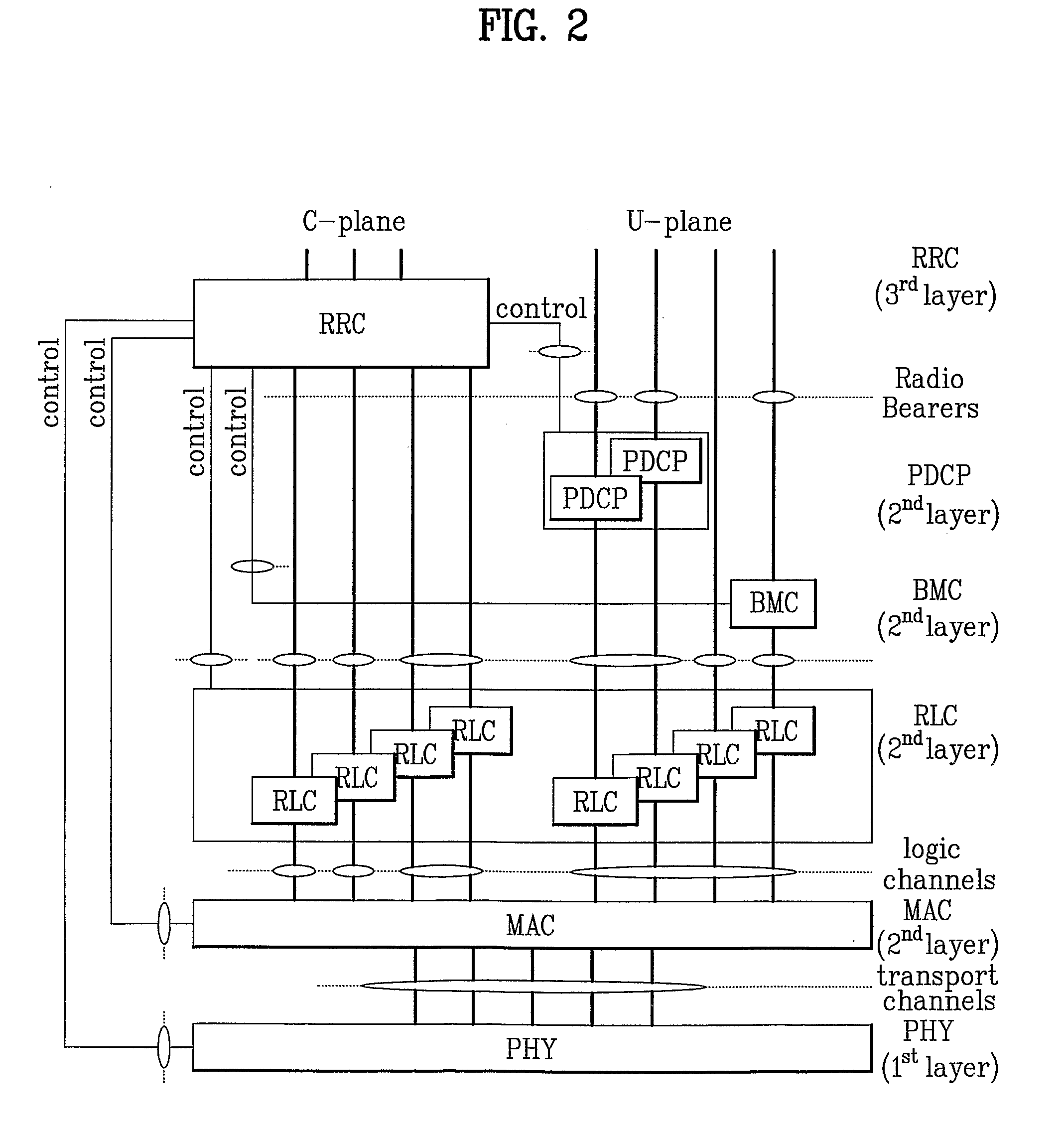
[0098]Embodiments in the following description are examples that technical features of the present invention are applied to the 3GPP mobile communication system. In particular, the following embodiments includes a method of generating a AM protocol data unit (AMD PDU) in an RLC layer of a communication system having a plurality of protocol stack structures including a physical layer, a MAC layer, the RLC layer and a PDCP layer using service data unit (SDU) and control information delivered from an upper layer, a transmitter thereof, a receiver thereof and a structure of the AMD PDU.

[0099]In the embodiment shown in FIG. 9, it is assumed that maximum two PDUs can be transmitted during one TTI (transmi...


PUM


Abstract

A method of generating a data block including control information in a specific layer of a mobile communication apparatus having a hierarchical structure constructed with a plurality of layers is disclosed. The present invention includes the steps of inserting a control data block including control information into a first region of a lower layer data block if the lower layer has the control information to be transmitted to a receiving side and inserting at least one portion of the data block of an upper layer into a second region of the lower layer data block, wherein the first region is allocated to the control data block before the second region is allocated to the at least one portion of the upper layer data block.

Description

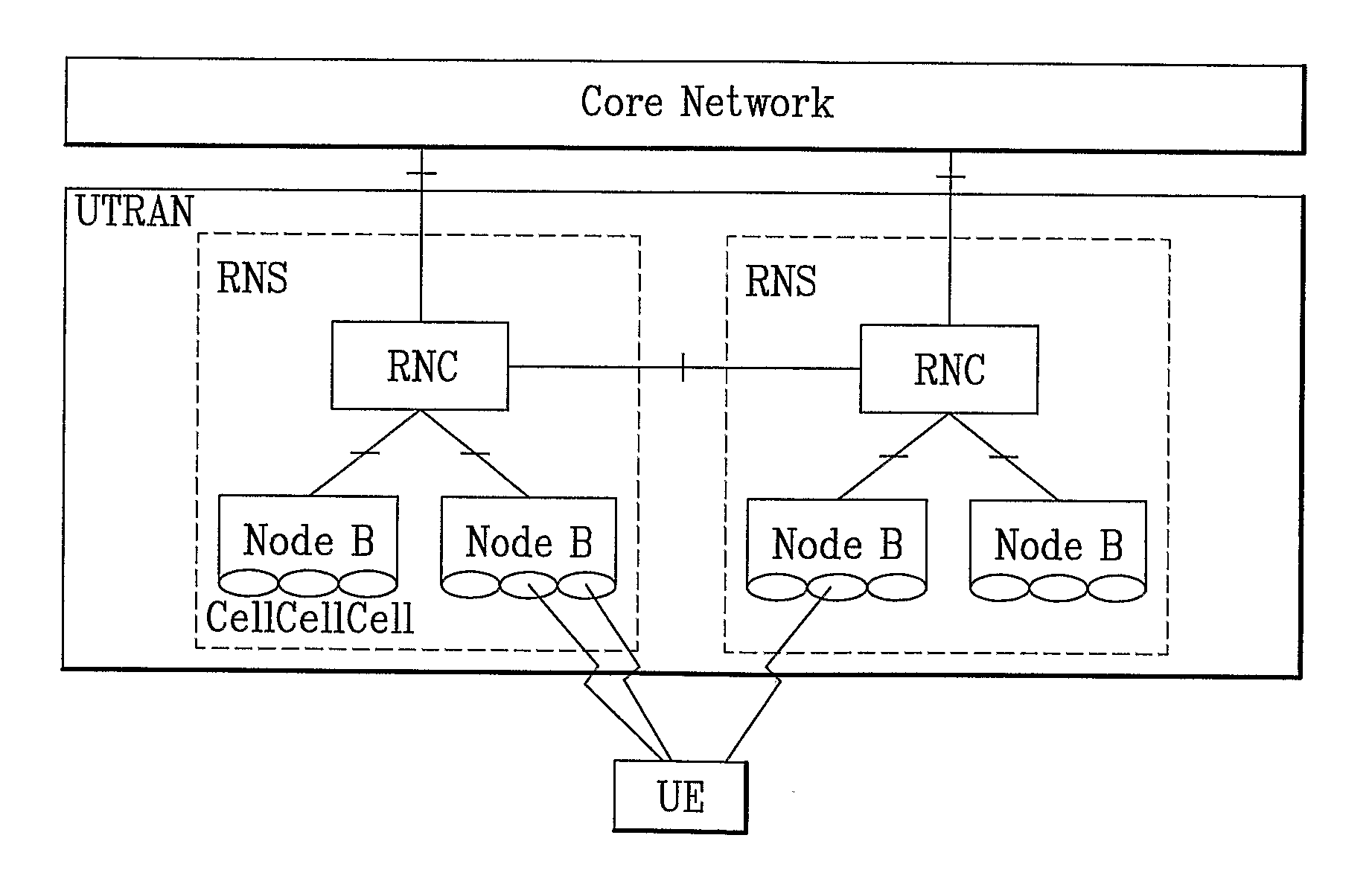
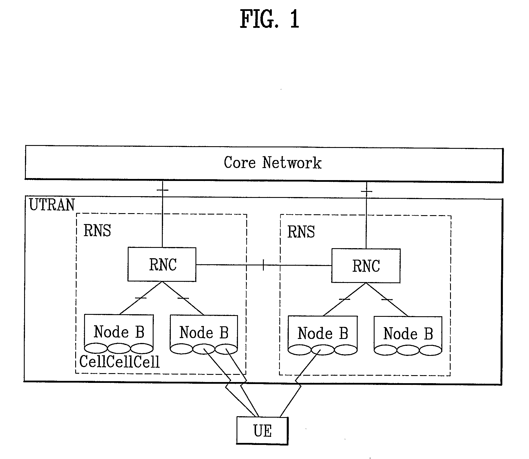
TECHNICAL FIELD[0001]The present invention relates to a wireless mobile communication system, and more particularly, to a method of generating a data block including control information in a specific layer of a mobile communication apparatus having a hierarchical structure constructed with a plurality of layers.BACKGROUND ART[0002]FIG. 1 is a diagram of a network architecture of UMTS (universal mobile telecommunications system) of an asynchronous IMT-2000 system.[0003]Referring to FIG. 1, a universal mobile telecommunications system (hereinafter abbreviated UMTS) mainly includes a user equipment (hereinafter abbreviated UE), a UMTS terrestrial radio access network (hereinafter abbreviated UTRAN) and a core network (hereinafter abbreviated CN).[0004]The UTRAN includes at least one radio network sub-system (hereinafter abbreviated RNS). And, the RNS includes one radio network controller (hereinafter abbreviated RNC) and at least one base station (hereinafter called Node B) managed by ...

Claims


Application Information

Patent Timeline
IPC IPC(8): H04Q7/00H04W28/00H04W28/06
CPCH04L1/1671H04L47/35H04W28/06H04L69/22H04L69/32
Inventor CHUN, SUNG DUCKLEE, YOUNG DAEJUNG, MYUNG CHEUL
Owner LG ELECTRONICS INC
Learn More