

Method for leak detection in heat transfer systems
a technology of heat transfer composition and leak detection, which is applied in the direction of fluid tightness measurement, lighting and heating apparatus, instruments, etc., can solve the problems of leakage in the system, leakage of the lower boiling (or higher vapor pressure) component, etc., and achieve the effect of reducing the vapor pressure of the heat transfer composition remaining inside the heat transfer system
- Summary
- Abstract
- Description
- Claims
- Application Information
AI Technical Summary
Benefits of technology
Problems solved by technology
Method used
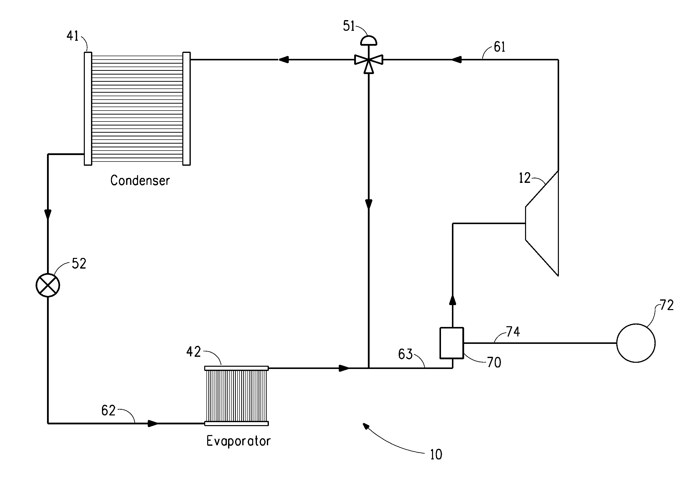
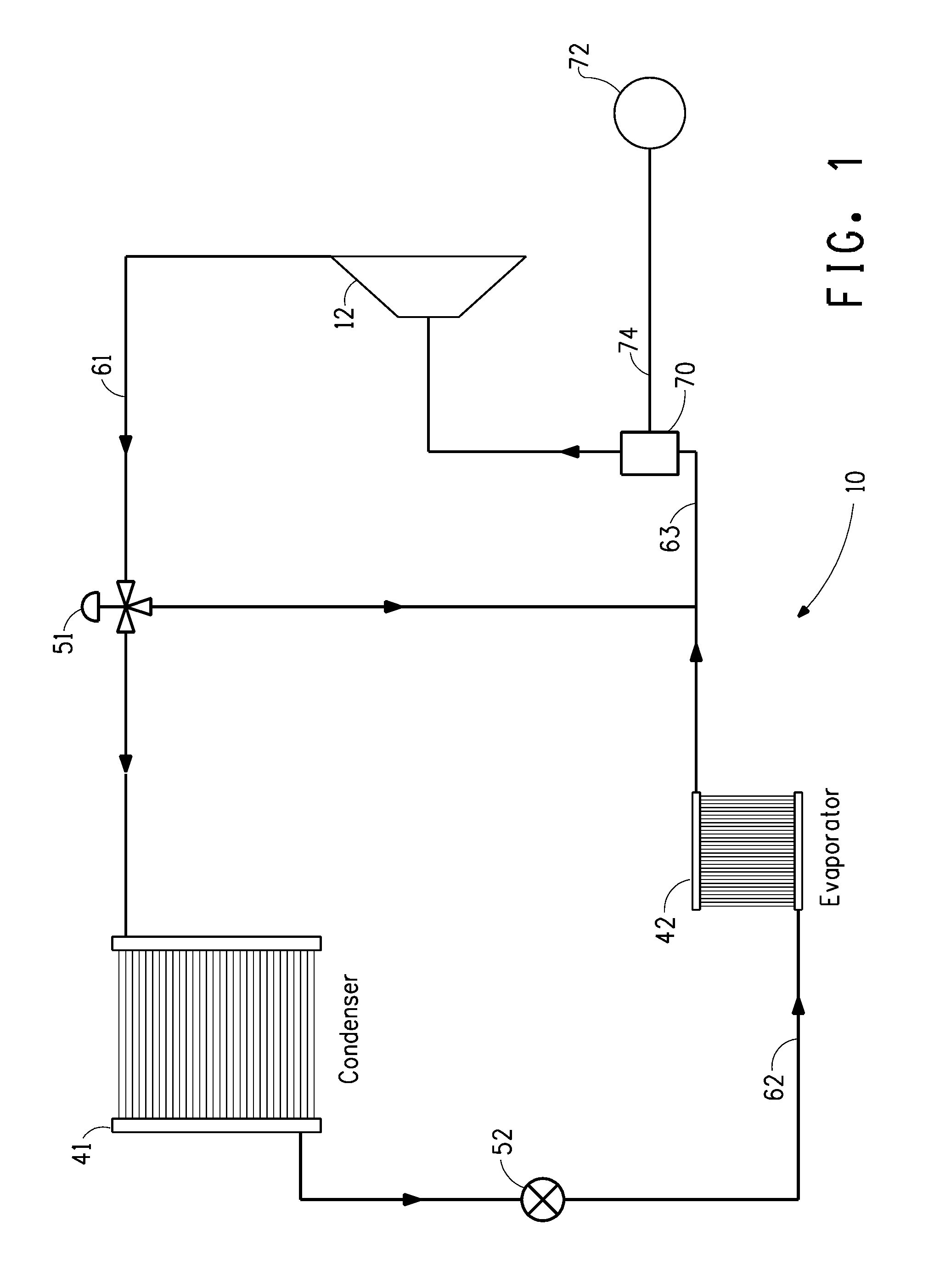
Image

Examples
example 1
Pressure Change During Leakage
[0101]A vessel is charged to 15% full (corresponding to a typical charge of an automobile air conditioning system) with an initial composition at a temperature of 23° C., and the initial vapor pressure of the composition is measured. The composition is allowed to leak from the vessel, while the temperature is held constant. The vapor pressure of the composition remaining in the vessel is measured at different levels of leakage (as percent of original composition leaked). Vapor pressures are determined at about 13%, 20%, and 30% leakage and are shown in Table 4.
TABLE 4%Vapor pressureInitial CompositionLeakage(psia)HFC-1225ye / HFC-320 (initial)87.79(95 / 5 wt %)13.887.322084.8930.181.19HFC-1225ye / HFC-134a / HFC-320 (initial)89.96(87 / 8 / 5 wt %)13.989.542087.353083.94HFC-1225ye / HFC-134a / HFC-320 (initial)83.45(88 / 9 / 3 wt %)13.483.152081.63079.4HFC-1225ye / HFC-134a / HFC-320 (initial)89.17(88 / 9 / 3 wt %)13.988.742086.473082.95
The measurable pressure change indicated in t...
example 2
Pressure Change During Leakage
[0102]A vessel is charged to 90% full with an initial composition at a temperature of 23° C., and the initial vapor pressure of the composition is measured. The composition is allowed to leak from the vessel, while the temperature is held constant. The vapor pressure of the composition remaining in the vessel is measured at different levels of leakage (as percent of original composition leaked). Vapor pressures are determined at about 10%, 20%, and 30% leakage and are shown in Table 5.
TABLE 5%Vapor pressureInitial CompositionLeakage(psia)HFC-1234yf / HFC-32 / HFC-1250 (initial)166.6(55 / 16 / 29 wt %)10163.820160.430156.5HFC-1234yf / HFC-1250 (initial)117.6(70 / 30 wt %)10116.520115.230113.7HFC-1234yf / propane0 (initial)112.3(95 / 5 wt %)10110.420108.330106.2HFC-1234yf / HFC-125 / HFC-0 (initial)119.2134a10118.2(50 / 30 / 20 wt %)20117.130115.9
The measurable pressure change indicated in the table provides a means for detecting a leak in a heat transfer system after minimal lo...
example 3
Pressure Change During Leakage
[0103]A vessel is charged to 90% full with an initial composition at a temperature of 23° C., and the initial vapor pressure of the composition is measured. The composition is allowed to leak from the vessel, while the temperature is held constant. The vapor pressure of the composition remaining in the vessel is measured at different levels of leakage (as percent of original composition leaked). Vapor pressures are determined at about 10%, 20%, and 30% leakage and are shown in Table 5.
TABLE 6%Vapor pressureInitial CompositionLeakage(psia)HFC-trans-1234ze / HFC-0 (initial)155.932 / HFC-12510152.1(55 / 16 / 29 wt %)20147.530142.1HFC-trans-1234ze / HFC-1250 (initial)108.4(70 / 30 wt %)10105.620102.33098.6HFC-trans-1234ze / propane0 (initial)90.9(95 / 5 wt %)1087.52083.73079.9HFC-trans-1234ze / HFC-0 (initial)111.5125 / HFC-134a10109.4(50 / 30 / 20 wt %)20106.930104.0
The measurable pressure change indicated in the table provides a means for detecting a leak in a heat transfer syst...
PUM
 Abstract
Description
Claims
Application Information