
Fluorescence calibrator for multiple band flat field correction

a calibrator and fluorescence technology, applied in calibration apparatus, instruments, optical radiation measurement, etc., can solve the problems of systematic errors, systemic errors, and spatial non-uniformities of both irradiation and imaging, and achieve the effect of reducing interference effects and reducing interference effects

Inactive Publication Date: 2008-12-25
BRUKER BIOSPIN
View PDF7 Cites 18 Cited by
  • Summary
  • Abstract
  • Description
  • Claims
  • Application Information

AI Technical Summary

Benefits of technology

[0009]The invention in one or more of its preferred embodiments features a fluorescence reference as a calibrating datum for fluorescence spectroscopic instruments having optical systems for directing fluorescent emissions from epi-illuminated assays onto detector arrays. The fluorescence reference, which can be substituted in place of the assays, contains multiple fluorescent agents over a range of excitation and emission wavelengths. The fluorescence agents are separated into layers with uniform distributions, and the layers are ordered in the form of a stack so that fluorescent agents with emission wavelengths that excite other fluorescent agents are located closer to both a source of illumination and the imaging system (i.e., in the shallower layers) than the other fluorescent agents that are excited by the emission wavelengths. Thus, the fluorescent emissions from fluorescent agents within any given layer do not appreciably excite fluorescent agents in any intervening layers en route to the detector array. As a result, the fluorescent emissions within the numerical aperture of the imaging system can reach the detector array without being diminished by absorption through fluorescent agents of intervening layers.
[0012]For typical Stokes-shifting fluorescent agents, the ordered layers can be arranged to function as a succession of band-stop filters that attenuate wavelength bands that progressively shift toward higher wavelengths with increasing depth. Both the excitation and the emission wavelengths of the fluorescent agents in successively deeper layers shift toward the longer wavelengths so that the desired excitation wavelengths reach the deeper fluorescent agents and the emission wavelengths from the fluorescent agents reach the imaging system. Other attenuation patterns, such as band-stop patterns, can be used for other combinations of fluorescent agents having excitation and emission wavelengths that vary somewhat differently in progression. The attenuation bands for successive layers provide a cumulative attenuating effect for the deeper layers.
[0016]Diffuse interfaces can be formed between the layers of the stack for reducing interference effects between the layers. For example, the diffuse interfaces can be formed by intervening layers that separate the layers containing fluorescent agents. The layers themselves can be formed by resin substrates within which the fluorescent agents are embedded in the form of dyes. Cover layers can be laminated to opposite sides of the resin substrates.
[0017]As an alternative to the diffuse interfaces, a refractive-index-matching material can be placed between adjacent layers for reducing interference effects between the layers. The refractive-index-matching material can comprise a refractive-index matching adhesive.
[0018]An opaque layer is preferably appended to the bottom of the stack to prevent stray light from entering the stack. The opaque layer can be formed by a diffusely reflective material for redirecting emissions from the fluorescent agents toward the top of the stack. A rigid transmissive substrate can be appended to the top of the stack. Preferably, the rigid transmissive substrate is made of anti-reflective glass.

Problems solved by technology

Systematic errors arise from spatial non-uniformities associated with both the irradiation and imaging of the assay mediums.
Systematic errors can arise as field anisotropies among these requirements for uniform irradiance.
Systematic errors associated with imaging include optical aberrations such as field curvature, distortion, and chromatic aberration, as well as detection errors such as absorbance errors, dark field error, and variations in detection efficiency.
However, combinations of fluorescent agents with overlapping excitation and emission wavelengths can produce interactions that obscure the individual contributions of fluorescent agents.

Method used


Image

  • Fluorescence calibrator for multiple band flat field correction
  • Fluorescence calibrator for multiple band flat field correction
  • Fluorescence calibrator for multiple band flat field correction

Examples


Embodiment Construction

[0031]The following is a detailed description of the preferred embodiments of the invention, reference being made to the drawings in which the same reference numerals identify the same elements of structure in each of the several figures.

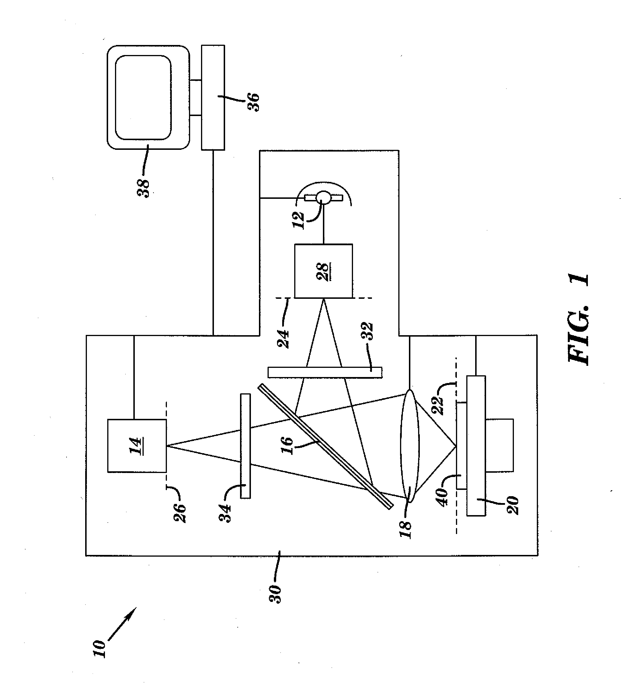
[0032]A fluorescence spectroscopic instrument 10 compatible with the invention is shown in FIG. 1 including a light source 12 capable of producing a range of excitation wavelengths and a detector array 14 capable of detecting relative intensities of a range of emission wavelengths. A beamsplitter 16 connects both the light source 12 and the detector array 14 to a common imaging system 18 that is focused above a sample stage 20. The entire light path originating at the light source 12, traversing the sample stage 20 (albeit converted to other wavelengths), and ending at the detector array 14 is fully enclosed within a light-tight housing 30 or other enclosure, which prevents stray light from entering the light path or otherwise reaching the detector ...


PUM


Abstract

A fluorescence reference plate for a fluorescence spectroscopic instrument is arranged with fluorescent layers having different excitation and emission characteristics. The fluorescent layers are ordered in the form of a stack for providing a flat-field calibration standard over multiple bands of wavelengths.

Description

FIELD OF THE INVENTION[0001]The invention relates to fluorescence imaging, particularly for biological assay mediums containing fluorophores as autofluorescent content or as exogeneous labels associated with selected contents and, in particular, to calibrating such instrumentation with a fluorescence reference having uniform or otherwise spatially defined fluorescence properties.BACKGROUND OF THE INVENTION[0002]Fluorescence imaging provides a powerful tool for identifying and characterizing selected contents of assay mediums, particularly biological assays containing in vivo or in vitro contents of interest. Specific molecular structures, including individual proteins or nucleic acids, and cell types or tissues in the form of single or array-based assay mediums can be targeted to fluoresce for identification or characterization.[0003]Within typical fluorescence spectroscopic instruments, the assay mediums are (a) irradiated at predetermined wavelengths that excite fluorophores assoc...

Claims


Application Information

Patent Timeline
IPC IPC(8): G01N3/62
CPCG01N21/278Y10T428/24942G01N21/6456
Inventor FEKE, GILBERTVIZARD, DOUGLAS L.
Owner BRUKER BIOSPIN
Learn More